Adding 3D Features
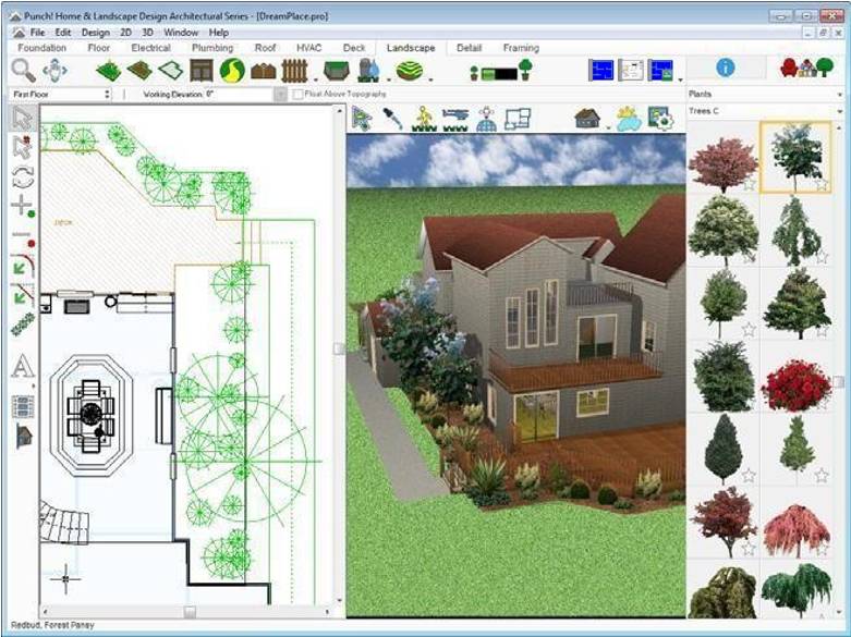
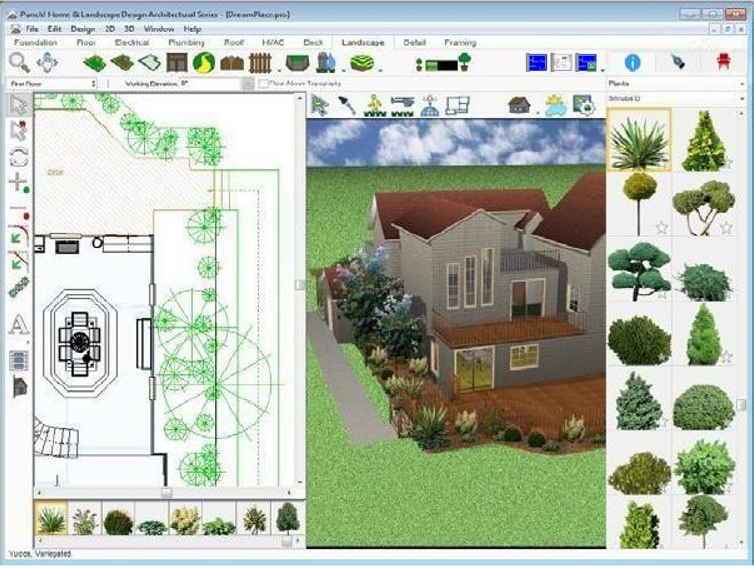
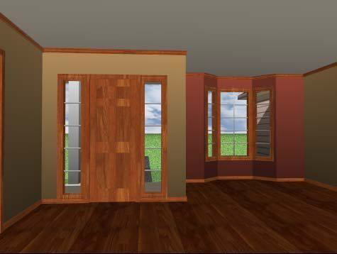
FloorPlan Home & Landscape Software lets you view your home in a fully-rendered 3D view. You can select exterior and interior wall color, add realistic roof materials, and select from a variety of woods to make your home design completely unique. View all your customizations in the 3D View Window.
By adding color, trim, and materials, you can make decorative changes to the 3D presentation of your home design as quickly as you think of them. This makes it easy to experiment with a variety of colors, both inside and outside your home, before picking up a paintbrush!
Note: Please note that not all features in this User's Guide are available in every FloorPlan Software title. Some features such as Photo-realistic rendering are available only in FloorPlan Pro.
Organizing Library Content
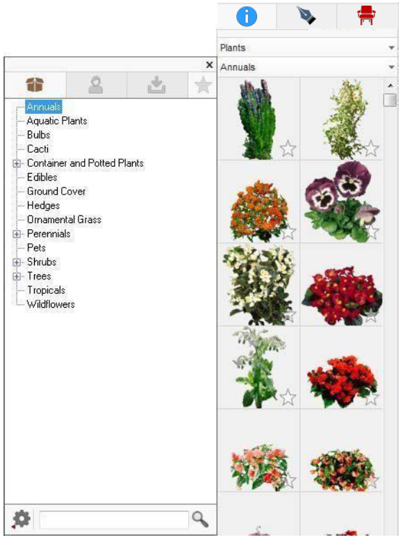
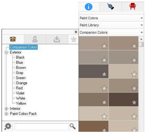
The Categories drop-down menu for each library includes three content libraries and a favorites list.
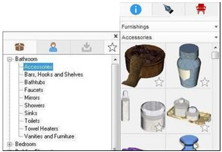
Stock Library
The Stock Library includes content that is delivered with the initial installation of the software. This content cannot be edited directly; however, you can copy these items to the User Library for editing, and/or add them to the Favorites list.
Note that different FloorPlan Home & Landscape titles include different Stock Libraries.
User Library
The User Library is populated when you copy items from another library to the User Library, either from within the application or in Windows Explorer. The User Library is also populated with objects and components you save using the PowerTools, for example Door Designer. When items are copied from a Stock Library, you can edit the object.
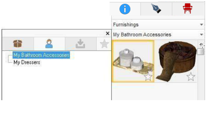
User Library content must be organized by category, so when you copy an item to the User library, you must choose a category or create a new category. You can choose to have one category for all your User Library content or create multiple categories, and sub-categories, to organize your content.
There are two methods for creating a category:
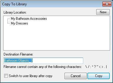
- When you right-click an item in the application and choose Copy to User Library, the Copy to Library window is displayed. Any categories that you’ve already created in this library are listed in this window, and you can choose one of them if you want to copy the item to one of the categories.
To create a new category, click the New button and choose to either create a new top-level category or select one of the existing categories to create a sub-category below it.
- Using Windows Explorer, you can create and delete folders to manage categories in the User Library folder. The User Library folder location in Windows Explorer is: C:\Users\
\My Documents\IMSI Design\User Library. Once a category exists, you can then copy content into the folder and it will be available in the application.
When copying an object from another version of Punch! software, there are three files that need to be included:
.pob file, .pod file, and .ppv file. If any of these is missing, the object will not copy successfully.
Note: When you add content to the User Library category folders, the content files must exist in a folder where no subfolders exist. For example, you can create a category named “Patio Pavers” and then add the content files to that category, but you cannot add files to that category and also create more folders for “light patio pavers” and “dark patio pavers.”
To create a new category when copying an item
- Right-click an item in the Preview bar and choose Copy To User Library. The Copy to Library window is displayed.
- Click the New button then choose New Category Here to create a new top-level category or choose an existing category to create a sub-category, and then click OK. The Category Name dialog box is displayed.
- Type a name for the category and then click OK.
- Select the library where you want to copy the item and then click the Copy button.
To create a new category in Windows Explorer
-
In Windows Explorer, browse to the following folder location > C:\Users\
\Documents\IMSI Design\User Library. -
Double-click the folder for the library where you want to add a category.
-
Click the New Folder button and type the category name and then press ENTER.
You can create sub-categories inside the new category folder to further organize content.
To delete category
-
In Windows Explorer, browse to the following folder location: C:\Users\
\Documents\IMSI Design\User Library. -
Delete the category or sub-category you want to remove.
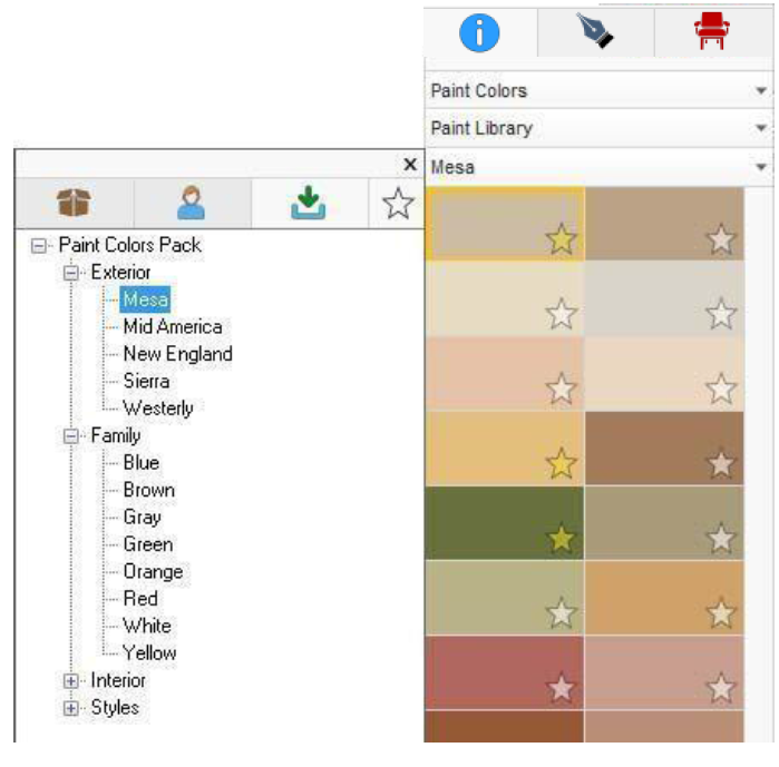
Downloaded content library
Occasionally, new library content becomes available and can be installed via content pack. This is considered downloaded content. Downloaded content is automatically added to its own folder within the User Library folder, which you can access by clicking the Downloaded content tab on the Categories drop-down menu.
To download content packs
-
Select the desired content pack. Most content packs must be purchased.
-
Navigate to the folder location where the content pack EXE was downloaded and double-click the file to start to content installation. The Welcome window is displayed.
-
Click Next and then click Finish to complete the installation. The content pack is automatically added to the “DLC” folder in the User Library for the relevant category.
Favorites List
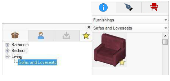
The Favorites list gives you the flexibility to compile items that you like, or plan to use later, to your Favorites as you browse through content categories. You can also populate your Favorites list with all of the items you may want to add to a particular room or area of your design and then add them all at once without having to search the Preview bar for the item you want. When you tag an item as a Favorite, a yellow star appears so you can see that it is a Favorite, and the item is added to your Favorites list.
The contents in the Favorites list is relative to the library where they exist. For example, if you add some paint colors to the Favorites list, you won’t see those in the Favorites list while you’re in the Furnishings library; when you’re in the Furnishings library, only items added to the Favorites list from Furnishings are visible. As you add items to your Favorites list, they are organized using the same category / sub-category structure that exists in the Categories drop- down menu.
To add or remove Favorites
- Click the star in the bottom-right corner of an item thumbnail to add it to the Favorites list. To remove an item from the Favorites list, click the star again to deselect it. (alternatively) You can also right-click an item to add or remove it from the Favorites list.
To access the Favorites library
-
Click the Libraries tab and choose the library you want from the Libraries drop-down menu.
-
Click the Content drop-down menu and click the Favorites tab. The items that have been added to the Favorites library are displayed in the Preview bar.
To hide the library, click the Favorites tab again.
Using the ProjecTape
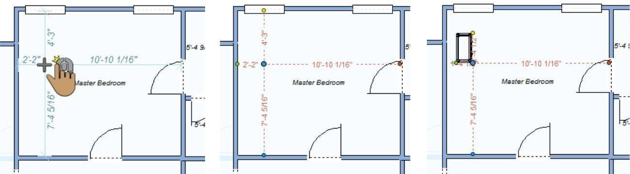
FloorPlan Home & Landscape Software’s ProjecTape helps you position plants, furniture, retaining walls, and more, exactly where you need them, the first time! The ProjecTape displays the dimensions from its center point to each of the four nearest objects or surfaces, allowing you to measure from multiple surfaces at once and specify the exact position you are looking for. Once placed, you can reposition the ProjecTape manually or by specifying values.
In the example below, the ProjecTape is used to position the corner of a nightstand a specific distance from two walls.
To position the ProjecTape
-
On the Edit Toolbar, click the ProjecTape Tool.
-
Move the cursor around the design window to see the distance to each of the nearest surfaces or objects. When the center of the ProjecTape is positioned where you want it, click to place it in your design.
Once placed, drag the center point to move the ProjecTape to a new position or use your arrow keys to nudge it incrementally in a specific direction.
Note: When you adjust one end point, the other points are affected.
To reposition the ProjecTape by a specified distance
- Click the Selection Tool and then click to select the center point of the ProjecTape. Its properties are displayed on the Properties tab.
When the ProjecTape is selected, you can reposition it by rotating a specified amount or incrementally. You can also reposition the ProjecTape by defining the distance the center point should be from each of its end points.
- Rotation Angle value determines the angle of the ProjecTape, which rotates from 0 to 359 degrees, in a counter-clockwise direction. Type a value in the Rotation Angle field and press the ENTER key or click the Rotate buttons to rotate theProjecTape in increments of 1-degree in the desireddirection.
- Detections setting specifies whether dimensionsare measured from Wall Surfaces or WallCenters.
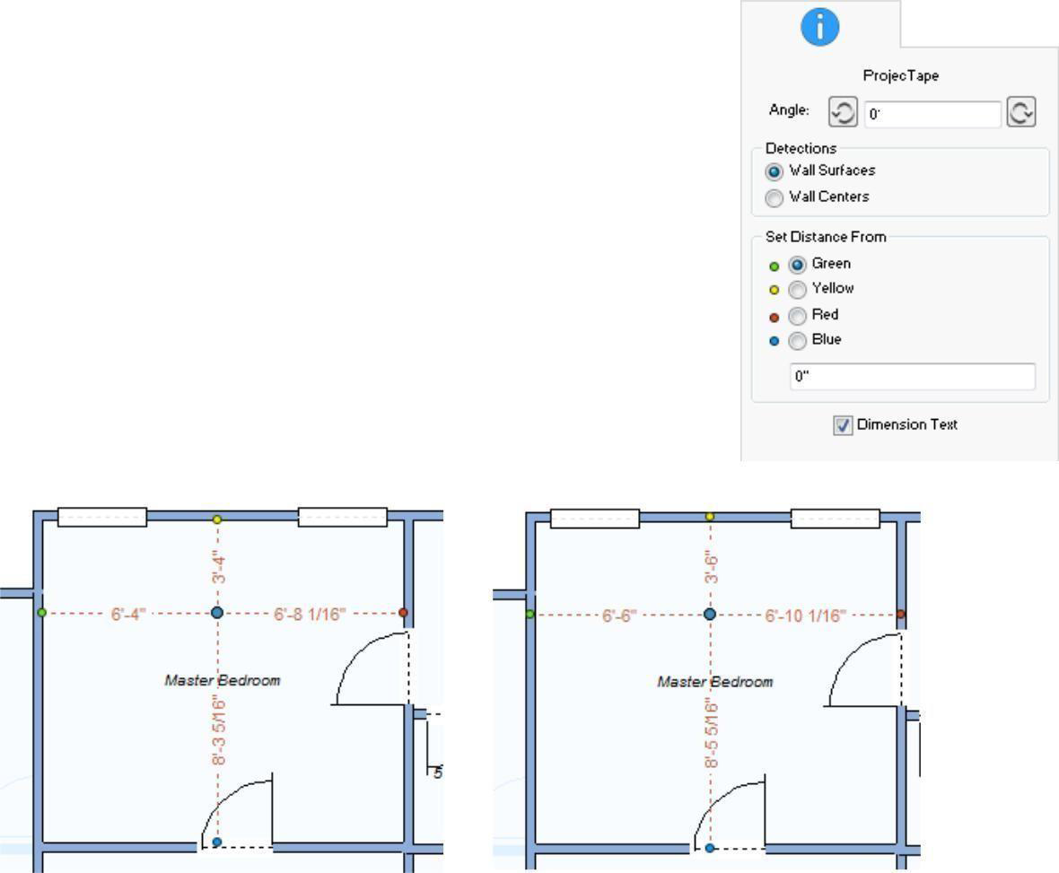
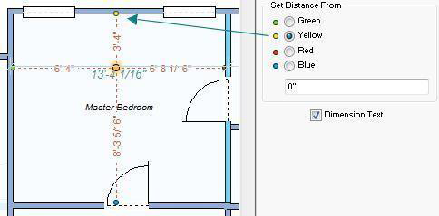
- Set Distance From allows you to specify the distance from a selected point to the ProjecTape center point. Each point on the Properties tab corresponds to a color-coded end point in the design. For example, the Yellow point is selected so the distance that is entered is applied to the length between the center point and the yellow point.
Dimension Text controls the visibility of the ProjecTape dimensions.
When selected, dimensions are displayed. When deselected, dimensions are hidden.
To turn off the ProjecTape
Click to select the center point of the ProjecTape and press the
DELETE key to remove the ProjecTape from your design.
3D Objects Libraries
With FloorPlan Home & Landscape Software, you can add details to the 2D drawing and 3D view presentation of your design using a variety of objects. The 3D objects are available in the Furnishings library.
Furnishing includes many categories of objects for you to add to your design. When a category is selected its contents are displayed in the Preview Bar. You can then drag-and-drop an object into your design. There are also a number of library options for organizing content as you design. You can add objects from any of the available content libraries or favorites list. For more information on the different content libraries, see “Organizing Library Content”. In addition to the content in the available libraries, you can import a Custom Workshop object or 3DS file that you have saved and then use that file in your design.
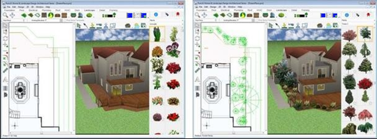
Note that, the contents of the libraries vary according with the different Punch! Home Design titles.
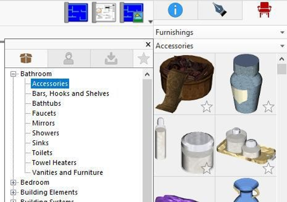
Full library
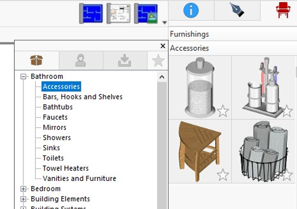
Partial library
Objects can be dropped into the design window or dropped into a 3D view window. When dropped into a 3D view, the object elevation is based on the location of your cursor. If dropped onto a floor or ceiling surface, the object is automatically placed at the surface elevation.
Objects only appear in 3D when you are viewing in 3D mode; in the design window objects appear as 2D symbols
The Furnishings library is accessible at any time and objects can be placed on any plan tab. Once placed in your design, 3D objects can be customized using 3D Custom Workshop.
To add 3D furnishing objects to your design
-
Click the Libraries tab and choose Furnishings from the Libraries drop-down menu.
-
Click the Categories drop-down menu and choose the Library tab and category you want to view. Its contents are displayed in the Preview Bar. Some of the categories are organized into sub-categories. Click to expand a category to see its contents.
-
Scroll through the available objects in the Preview Bar and drag-and-drop the one you want to place onto the design window or 3D view window.
Select the object you just placed to drag it to another location on your design window to position it as needed.
To import a 3D Custom Workshop object
-
Click File menu > Import > Punch! Custom Workshop Object. The Import Punch! 3D Object dialog box is displayed.
-
Find the file you want to import and then click to select it. Note: You can import .POB files only.
-
Click Open. The object is placed in the center of your 2D design.
-
Double-click the object to open it in 3D Custom Workshop.
To import a 3DS file
-
Click File menu > Import > 3DS File. The Import 3DS Design dialog box is displayed.
-
Find the file you want to import and then click to select it.
-
Click Open. The object is placed in the center of your 2D design. The Status Bar displays the progress, as the file is converted.
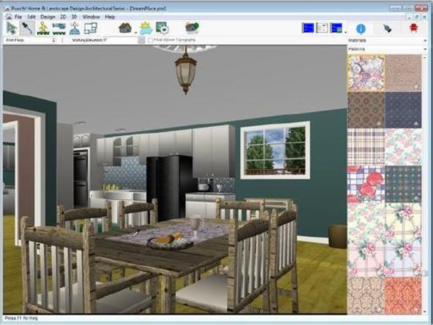
Editing 3D Objects
Once you’ve placed 3D objects in your drawing, it’s easy to move, delete, copy, and rotate objects, usually involving just one or two mouse clicks. In the example below, a dining set is selected in the 3D view and its properties are displayed on the Properties tab, including its rotation angle, sizing, and rendering options. You can also edit objects using 3D Custom Workshop.
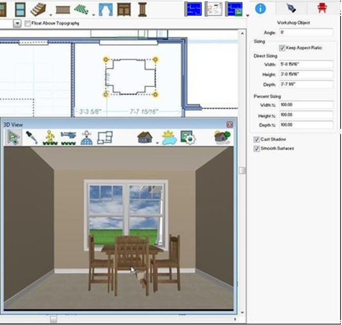
To resize an object
-
On the Edit Toolbar, click the Selection Tool and then click to select an object. Its properties are displayed on the Properties tab.
-
To resize the object proportionally when one of the dimensions is changed, select the Keep Aspect Ratio checkbox. To resize only the value you edit, deselect Keep Aspect Ratio.
-
Type the Width, Height, and Depth, in feet and inches or percentages, to customize them. Press ENTER to accept each new value.
(optional) Type an angle, if you want to rotate the object. Press ENTER to accept each new value.
To rename objects
-
On the Edit Toolbar, click the Selection Tool.
-
Right-click an object and choose Object Information from the context menu. The Custom Workshop Object Information dialog box is displayed.
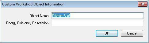
3- Type a new name in the Object Name text box then click OK.
Note: This is the name that is listed in the spreadsheet, created by Punch! Estimator.
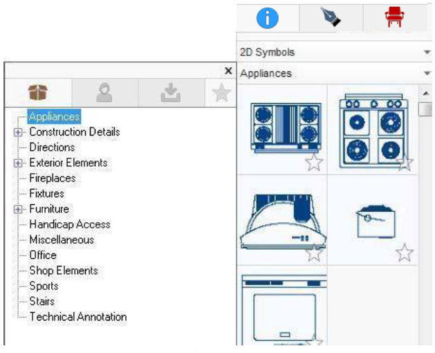
2D Symbols Library
A library of 2D symbols is available. These are visual representations you can add to your design that do not appear in the 3D view.
2D Symbols includes many categories of symbols for you to add to you design. When a category is selected its contents are displayed in the Preview Bar. You can then drag-and-drop a symbol into your design.
You can also add symbols from the User Library, Download Content, as well as Favorites list.
It is important to keep in mind that the objects only appear in 3D when you are viewing in 3D mode. In the plan drawing, objects appear as 2D symbols, while textures such as color, wallpaper, wainscoting, and other materials do not appear in 2D at all.
To add 2D symbols
-
Click the Libraries tab and choose 2D Symbols from the Libraries drop-down menu.
-
Click the Categories drop-down menu and choose the Library tab and category you want to view. Its contents are displayed in the Preview Bar. Some of the categories are organized into sub-categories. Click to expand a category to see its contents.
-
Scroll through the available symbols and drag-and-drop the one you want to place onto your design window.
Select the symbol you just placed to drag it to another location on your design window to position it as needed.
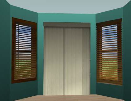
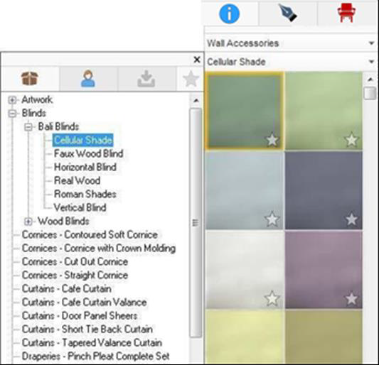
Wall Accessories Library
The Wall Accessories category is very large and includes artwork as well as drapes, blinds, curtains, and other window and door accessories, which should be used in conjunction with the Wall Accessory tool (available on the Floor plan tab).
The elements in the Wall Accessories library are applied to an existing accessory in the 3D view using drag-and-drop. Artwork, which is available from the Wall Accessories category, is applied to a wall in the 3D view using drag-and-drop.
You can edit the wall accessories to adjust their appearance. For more information on editing accessories, see “Editing Materials”
For information on adding accessories to your drawing, see “Adding Accessories”
To add wall accessories using drag-and-drop
-
Open a 3D view window and then click the Libraries tab and choose Wall Accessories from the Libraries drop-down menu.
-
Click the Categories drop-down menu and choose the Library tab and category you want to view. Its contents are displayed in the Preview Bar. Some of the categories are organized into sub-categories. Click to expand a category to see its contents.
-
Scroll through the available wall accessories and drag-and-drop the one you want to place; onto an accessory in the 3D view window.
If SmartWand is enabled, choose how you want the accessory applied. For more information, see “Using the SmartWand”
Plants Libraries
Thousands of plants are included with FloorPlan Home & Landscape Software, which makes designing your landscape easy and fun.
Divided into several categories, choose the ones that grow best in your region.
In addition to the content in the available libraries, you can import a plant image and a corresponding plant information file to add your own plant(s) to the library.
Plants can be dropped into the design window or dropped into a 3D view window. When dropped into a 3D view, the plant elevation is based on the location of your cursor. If dropped onto a floor or ceiling surface, the object is automatically placed at the surface elevation.
Tip: Hover your cursor over the preview of the plant its name is displayed in the Status Bar.
Note: You can see all of the plants in your drawing by showing the Plant Inventory Bar. For more information, see “Plant Inventory Bar”
Below are some references that may be helpful as you design:
■ Plant Properties
■ Elevating Objects
■ Viewing Hardiness Zones
■ Growing the Landscape
■ Adding a Visual Array
■ Filling a Shape with Plants
To add plants
-
Click the Landscape plan tab and then click the Libraries tab and choose Plants from the Libraries drop-down menu.
-
Click the Categories drop-down menu and choose the Library tab and category you want to view. Its contents are displayed in the Preview Bar.
-
Some of the categories are organized into sub-categories. Click to expand a category to see its contents.
-
Scroll through the available options and drag-and-drop the plant you want to place onto your design window or onto your 3D view window.
To view plant description, requirements, and growth information
- On the design window, right-click the plant and choose Plant Details on the context menu. The Plant Details window is displayed, showing the available information for that plant.
To edit plant description, requirements, and growth information
- Copy the plant to the User Library. For information on working with the different libraries, see “Organizing Library Content”
- Navigate to the plant preview in the User Library Preview bar, then right-click the plant and choose Edit Details. The Plant Details dialog box is displayed.
- Edit the details you want to change and then click OK.
To import a plant
-
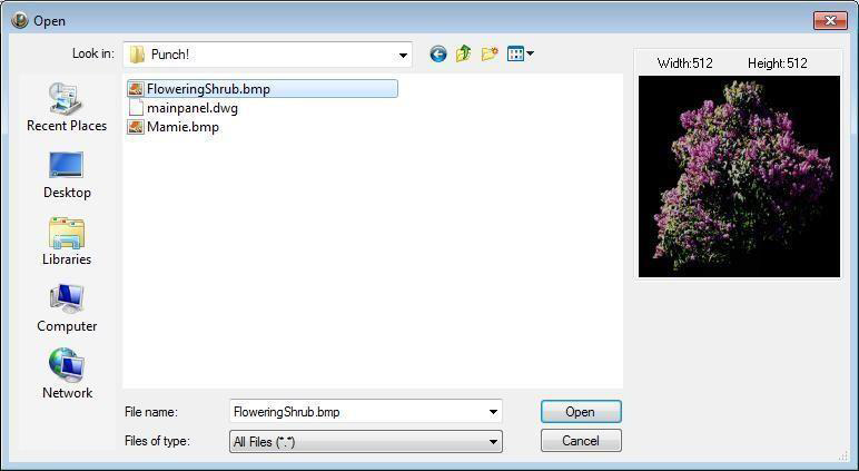
Click File menu > Import > Plant to Library. The Open dialog box is displayed.
-
Find the file you want to import and then click to select it. A preview is displayed.
-
Click Open. The Plant Import Wizard welcome page is displayed. (optional) Click Import to import an information file (. pti file) for this plant.
-
Click Next. The Description page is displayed.
-
Type characteristics in the corresponding fields to describe the plant you are importing and then click
6- Click Open. The Plant Import Wizard welcome page is displayed.
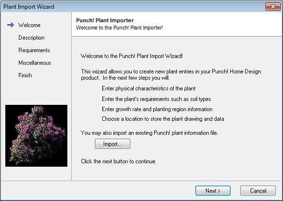
(optional) Click Import to import an information file (. pti file) for this plant.
7- Click Next. The Description page is displayed.
8- Type characteristics in the corresponding fields to describe the plant you are importing and then click Next. The Requirements page is displayed.
9- Specify the plant’s requirements, such as sunlight, water, and soil type, and then click Next. The Miscellaneous page is displayed.
10- Specify the planting zone and growth rate, and then click Next. The Finish page is displayed.
Note: For more information on regional and temperature requirements, see “Viewing Hardiness Zones”
11- Choose the Plant Category where you want to import the plant or click the New button to create a new category or sub-category.
Note: Some categories have sub-categories. Simply expand the main category to see the sub- categories.
(optional) Type a new name in the Save File As field.
12- Click Finish. The plant is imported based on the details you’ve provided and is displayed in the preview bar automatically.
The plant details can be edited in the Plant Details dialog box. For more information, see “To view plant description, requirements, and growth information”
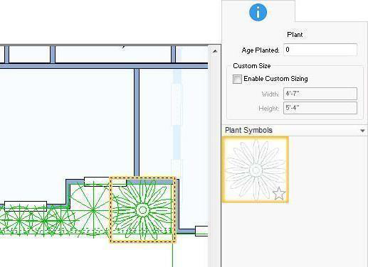
Plant Properties
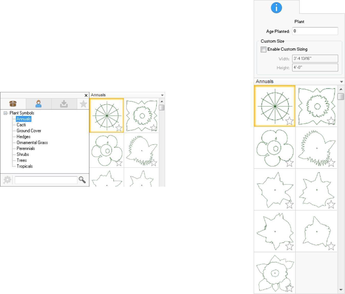
When a plant is selected in the design window, you can edit the plant's age, customize its size, and even customize the 2D appearance by selecting different plant symbols. For information on growing the entire landscape, see “Growing the Landscape”
- Age Planted You can specify the age of each plant individually to affect maturity one plant at a time (or select a few and update them together).
- Enable Custom Sizing allow you to edit the width and height for the plant. The size is an absolute size for the whole plant.
- When custom sizing is enabled, the plant is not affected by the plant growth slider or planting age; however, the planting age is still displayed in Estimator
- Plant symbols library allows you to choose the 2D symbol you want for the plant. You can choose from the stock libraries or the User Library, where you can save plant symbols you've created or symbols you've copied.
Creating Plant Symbols
Plants are represented in 2D by a default plant symbol. You can customize the plant symbol to give each plant or type of plant a unique look. This is useful if you have a lot of different plants in your design so you can quickly differentiate and identity plants in 2D. Plant symbols are available on the Properties tab when plant is selected, or you can draw a custom plant symbol using the 2D shapes on the Detail tab and then save the symbol to use in your design.
To apply a plant symbol, see “Plant Properties”
Symbols are drawn using the 2D drawing tools. For more information on using these tools, see “Detail Plan Tab”
To create a plant symbol
-
Using the 2D shapes on the Detail plan tab, draw a plant symbol you want to save.
-
Select the entire shape you want to use for a plant symbol.

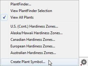
3- Click the Content tab and choose Plants from the library drop-down menu.
4- Click the categories drop-down menu and, at the bottom of the menu, click the gear button and choose Create Plant Symbol. The Save Plant Symbol To Category window appears.
5- Choose the category (or create a new one).
6- Edit the name and description and then click Save To Library. The symbol is added to the User Library.
Plant Inventory Bar
FloorPlan Home & Landscape Software keeps track of which plants you have used in your landscape. The Plant Inventory Bar shows all plants that are on the visible plan and on the active floor. From this bar, you can easily find and/or replace all occurrences of each plant in your design.
When the Plant Inventory Bar is visible, you can select all occurrences of a plant in your design, delete plants from your design, and replace plants in your design by dragging a different plant onto an existing plant in the Plant Bar.
To access the plant inventory bar
- Click Design menu >Show Plant Bar. The
Plant Inventory Bar is displayed across the bottom of the design window.
To select all occurrences of a plant
- On the Plant Inventory Bar, double-click a plant. All occurrences of that plant are selected in the plan.
To delete a plant
- On the Plant Inventory Bar, right-click a plant and choose Delete Plants. All occurrences of that plant are deleted from the design.
To replace all occurrences of a plant
- On the Preview Bar, click the plant you want to use; hold down the mouse button and drag it onto the plant you want to replace on the Plant Inventory Bar. All occurrences of that plant are updated in the design.
Viewing Hardiness Zones

FloorPlan Home & Landscape Software includes USDA Hardiness Zone maps for the contiguous 48 states, Alaska and Hawaii, Canada, Europe, and Australia. All of the maps are available from the Plants
The zones in the hardiness zone map correspond to the zones listed in the plant details for each plant, so you can easily find the ideal plants for your location. All plants included in FloorPlan Home & Landscape Software can be sorted using this information.
For information on sorting plants see “Finding Plants”.
For steps to access plant details see “To view plant description, requirements, and growth information”
To view a hardiness zone map
-
Click the Libraries tab and choose Plants from the Libraries drop-down menu. The Plants categories become available.
-
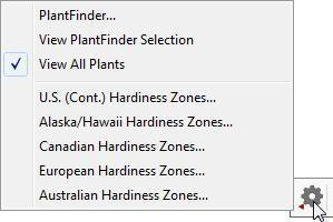
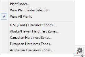
Click the Categories drop-down menu and, at the bottom of the menu, click the Options button. The Hardiness Zones are displayed on the menu.
-
Click the Hardiness Zone map you want to view.
To hide the hardiness zone map
- Click anywhere on the zone map.
Finding Plants
FloorPlan Home & Landscape Software includes thousands of plants to make designing your landscape easy and fun. PlantFinder is a powerful sorting engine that lets you see only the plants that fit your particular criteria. You can also find plants that are already in your design or by searching for a plant name.
Sorting Plants
By selecting the plant characteristics, you want and deselecting the ones you don’t want, you can filter the plants that are displayed in the Preview Bar for a selected plant category. Only the plants matching all the selected options are displayed in the Preview Bar.
Tip: To narrow your search, check fewer boxes.
To sort plants
-
Click the Libraries tab and choose Plants from the Libraries drop-down menu. The Plants categories become available.
-
Click the Categories drop-down menu and, at the bottom of the menu, click the Options button.
-
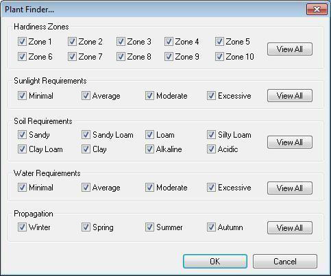
Choose PlantFinder from the Options menu. The PlantFinder dialog box is displayed.
-
Deselect the criteria that does not meet your needs or select the criteria you do need.
(optional) Click the View All buttons to select all options in a category.
5- Click OK. Only the plants matching all the variables selected are displayed in the Preview Bar when viewing a plant category.
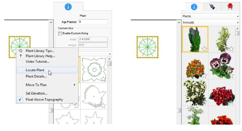
Locating a Plant in your Design
With so many plant options, you may lose track of where you found a plant that you’ve added to your design. There is an easy way to track down a plant from your design window or from a 3D view window.
To locate a plant in the design window
- In the design window, right-click the plant you want to locate and choose Locate Plant on the context menu. The plant category is displayed on the preview Bar and the plant is selected.
To locate a plant in the 3D view window
- In the 3D view window, click the Find Applied Tool and CTRL+click the plant. The plant category is displayed on the preview Bar and the plant is selected.
To find a plant by name

-
Click the Libraries tab and choose Plants from the Libraries drop-down menu. The Plants categories become available.
-
Click the Categories drop-down menu and, at the bottom of the menu, type the botanical or common name of the plant in the text field and click the Search button. Plants matching the criteria you specified are displayed in the Preview Bar.
To view all plants
- Click the Plants library drop-down menu and, at the bottom of the menu, click the Options button and choose View All Plants
Growing the Landscape
With FloorPlan Home & Landscape Software you can watch your landscape grow from year to year. With just a couple of mouse clicks you can watch your landscape change over 20 years. The Plant Growth meter allows you to grow all of your landscape together incrementally, one click at a time. The Plant Growth meter is available on the Landscape plan toolbar.
To edit the age planted for individual plants, see “Plant Properties”.
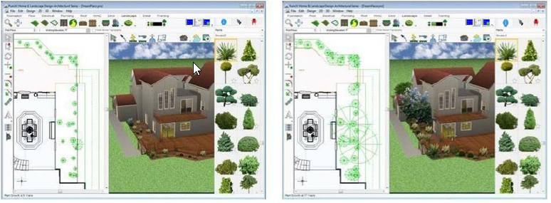
To grow your landscape incrementally
- Open a 3D view window and position it to easily see the area of your landscape you want to watch mature.
2- Click the Landscape Tab. The Plant Growth Meter is displayed to the right of the plan tools.
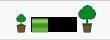
3- Clicking the smaller tree to the left of the Plant Growth Meter makes the plants appear younger, while clicking the larger tree, on the right, makes them appear older.
The age is displayed in the Status Bar as you click the Plant Growth Meter.
To set the maximum growing age
-
Click Design menu > Plant Growth Projection. The Design Options dialog box opens to the General design settings.
-
Under the Plant Growth Projection section, type the maximum growing age for plants in the Grow To text field and click OK. Plants grow to the age you’ve specified.
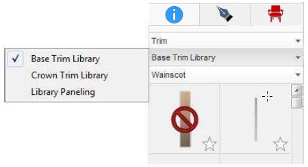
Applying Trims
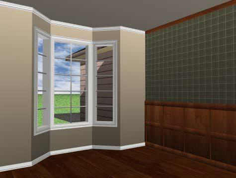
It is easy to add base trim, crown molding, or library paneling for an elegant appearance or use wainscoting if you want to apply two different materials on one wall.
You can also add case molding around doors and windows and even apply trim to the top of cabinets for a completely unique look. All of these customizations are made in the 3D view window.
Trim is applied to directly to the surfaces in the 3D view using drag-and-drop. You can change a trim style by applying a new style right on top of an existing style and even remove trim after it has been applied.
There are three trim styles available from the Trim library:
- Base Trim
- Crown Trim
- Library Paneling
The Base Trim Library and Crown Trim Library include categories of trim, including window and door casing styles. The Library Paneling library includes various heights of paneling to apply to your design.
To apply base trim and crown trim
-
Click the Libraries tab and choose Trim from the Libraries drop-down menu. The Trim Type libraries become available.
-
Click the Trim Type library drop-down menu, then choose Base Trim Library or Crown Trim Library. The trim style categories are displayed.
-
Click the Categories drop-down menu and choose the Library tab and category you want to view. Its contents are displayed in the Preview Bar.
-
Scroll through the available trim options and drag-and-drop the one you want to place onto a surface in the 3D view window.
To apply library paneling
-
Click the Libraries tab and choose Trim from the Libraries drop-down menu. The Trim Type libraries become available.
-
Click the Trim Type library drop-down menu, then choose Library Paneling. Its contents appear in the Preview Bar.
-
Scroll through the available trim options and drag-and-drop the one you want to place onto a surface in the 3D view window.
To remove wall trim
-
Click the Libraries tab and choose Trim from the Libraries drop-down menu. The Trim Type libraries become available.
-
Click the Trim Type library drop-down menu, then choose the trim type that you want to remove. The trim styles are displayed in the Preview Bar.
-
Drag-and-drop the Remove Trim style onto the wall from which you want to remove trim.

Applying Paint and Color
With FloorPlan Home & Landscape Software, you can try out various color schemes with ease. Now you can choose between paint libraries and color families with just a few mouse clicks. Walls are just one example of what can be colorized; you can also apply color to furniture, window trim, doors, and other surfaces. All of these customizations are made on the 3D view window.
There are three types of Paint Colors available:
- Custom Colors
- Color Ramp
- Paint Library
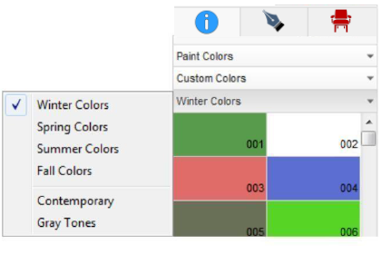
Custom Colours
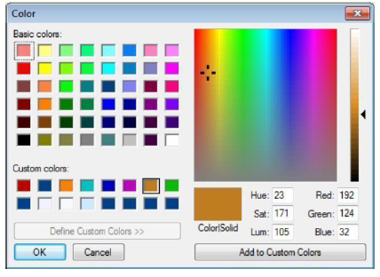
Custom colors are themed color groups, each containing colors that can be customized using the color dialog box. You can start with one of the basic colors available, then change the RBG composition (red, blue and green values), or double-click a color in the color spectrum windows to "mix" your own color.
In addition to customizing colors from the Preview Bar, you can add custom colors to your library. If you see a color you like, maybe a shade of green in the grass, or a fabric on a couch that is not currently available as a color, you can add that color to your library. For more information on adding custom colors, see “Identifying Colors and Materials in 3D View”.
To define a custom color
-
Click the Libraries tab and choose Paint Colors from the Libraries drop-down menu. The Paint Colors Type libraries become available.
-
Choose Custom Colors from the Paint Colors Type drop-down menu. The Categories drop- down menu becomes available.
-
Click the Categories drop-down menu and choose the category you want. Its contents appear in the Preview Bar.
-
In the Preview Bar, right-click the color you want to customize and click Choose Color (or double-click the color preview). The Color dialog box is displayed.
-
Click one of the Basic or Custom colors or click in the color spectrum block to select a color.
(optional) Adjust the current Hue, Saturation, and Luminosity, or Red, Green, and Blue values to create a custom color.
6- Click OK. The color you defined is displayed on the Preview Bar.
To apply the color, drag-and-drop the color onto a surface in the 3D view window.
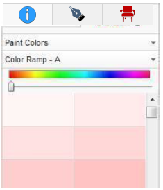
Color Ramp
The Color Ramp offers a spectrum of colors with twenty-five shades for each color option. To see the colors, drag the slider along the spectrum. The Preview Bar displays the shades that are available for each color.
To apply color from the color ramp
-
Click the Libraries tab and choose Paint Colors from the Libraries drop-down menu. The Paint Colors Type libraries become available.
-
Choose Color Ramp from the Paint Colors Type drop-down menu. The Color Ramp options become available. Twenty-five shades of the selected color are displayed in the Preview Bar.
-
Drag the slider, below the color spectrum, to change the color family.
-
Scroll through the available shades in the Preview Bar to view the variations of that color and then drag-and-drop the color you want onto a surface in the 3D view window.
Paint Library
The Paint Library includes interior and exterior groups of colors.
To make designing easier, you can create custom Decorator Palettes. For more information, see “Using the Decorator Palette”.
If SmartWand is enabled, you can choose to apply to the individual surface or to all similar surfaces. For more information, see “Using the SmartWand”.
There are a couple of ways to search for paint colors, including using keywords and using the Paint Chooser.Keyword Search is available on the Categories drop-down menu. Type the color you are looking for in the text box and click the Search button. All of the applicable colors are displayed in the Preview bar.
- Paint Chooser displays the active category all in one window with small thumbnails of the colors and a large preview of the selection.
You can change the active category by clicking the drop-down menu in the top-left corner of the window and choosing a different category. To view the category, you must click OK on the drop-down menu
To apply paint
-
Click the Libraries tab and choose Paint Colors from the Libraries drop-down menu. The Paint Colors Type libraries become available.
-
Choose Paint Library from the Paint Colors Type library drop-down menu. The Categories drop-down menu becomes available.
-
Click the Categories drop-down menu and choose the Library tab and category you want to view. Its contents are displayed in the Preview Bar. Some of the categories are organized into sub-categories. Click to expand a category to see its contents.
-
Scroll through the available paint colors and drag-and-drop the paint color you want onto a surface in the 3D view window.
Identifying Colors and Materials in 3D View
As you experiment with different colors and materials during the design process, you may want to identify a previously-used material. This is easy with FloorPlan Home & Landscape Software’s Find Applied Tool. You can also identify a color you like in your design and add it to the Custom Colors library.
Note: When adding a custom color, the color replaces the first color in the Gray Tones category. You can change the custom colors at any time. For more information on editing these colors, see “Custom Colors”.
Note: You can also use the Find Applied Tool to locate plants in the 3D View. For more information, see “Locating a Plant in your Design”.
The material identified in the example below is the placemat on the table.
To use the find applied tool
-
Open a 3D view window and click the Find Applied Tool.
-
In the 3D view window, click the color or material that you want to identify. That color or material is displayed in the Preview Bar.
To create a new color
-
Open a 3D View window and click the Find Applied Tool.
-
Press SHIFT and click the color you want to add. A dialog box is displayed.
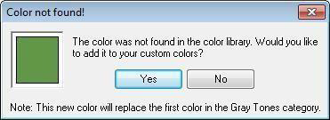
3- Click Yes to save the color to your Custom Colors library.
Applying Building Materials
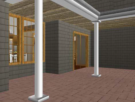
With FloorPlan Home & Landscape Software, customizing the materials of your home is a simple drag-and-drop procedure. Available materials include backgrounds, brick, stucco, gravel, roofing, and many more. You can even apply two different materials to a wall, using the Wainscoting feature. For more information, see “Applying Trims”.
You can create and import your own custom materials and background images. When importing materials, the User Library is the location where materials are imported. If you do not have a User Library folder created for Materials, you can create a new folder when importing. For more information on working with the libraries, see “Organizing Library Content”.
If SmartWand is enabled, you can choose to apply to the individual surface or to all similar surfaces. For more information, see “Using the SmartWand”.
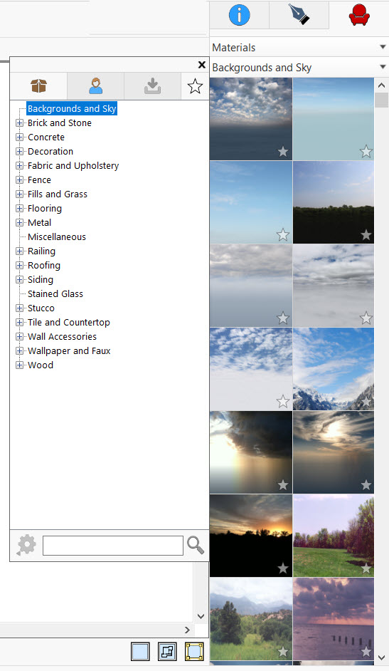
To apply materials
-
Click the Libraries tab and choose Materials from the Libraries drop-down menu. The Materials categories become available.
-
Click the Categories drop-down menu and choose the Library tab and category you want to view. Its contents are displayed in the Preview Bar. Some of the categories are organized into sub-categories. Click to expand a category to see its contents.
-
Scroll through the available materials and drag-and-drop the material you want to onto the desired surface in the 3D view window.
To import a material
- Click File menu > Import > Material to Library. The Open dialog box is displayed.
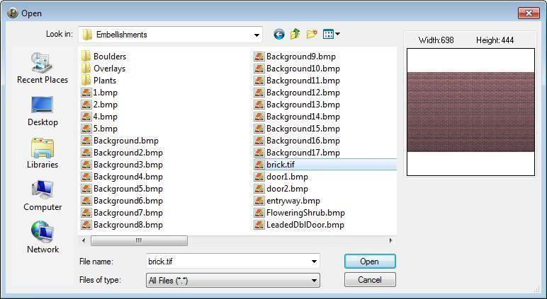
2- Find the file you want to import and then click to select it. A preview is displayed.
3- Click Open. The Material Importer dialog is displayed.
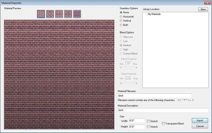
- In the Material Preview section, you can choose the number of tiles you want the material to have.
- Seamless Options control the seams on the edges of the material. Horizontal blends images along their sides; Vertical blends images along the top and bottom; Both blends horizontally and vertically; None does not blend.
- Blend Options control the distance and intensity of the blended edge. A lower blend option concentrates blending at the edges of the image. A higher blend option concentrates blending across the entire image. You can choose a predefined option or select Custom Blend to specify the distance and intensity.
- Filename and Description define the name and description of the material. New material descriptions can contain up to 78 characters.
- Size values control the width and height of the material. You can enter specific values for each direction or select the Stretch checkbox direction to automatically stretch the material in that direction to cover the surface where it is applied.
- Transparent Black checkbox designates all black areas (RGB=0,0,0) of the material image as transparent.
- Library Location specifies where you want to import the material. You can choose an existing User Library
category or sub-category or click the New button to create a new User Library category or sub-category.
4- Set the material options you want and then choose the Library Location where you want to save your new material, then click OK.
To import a 3D background
-
Click File menu > Import > 3D Background. The Open dialog box is displayed.
-
Find the file you want to import and then click to select it. A preview is displayed.
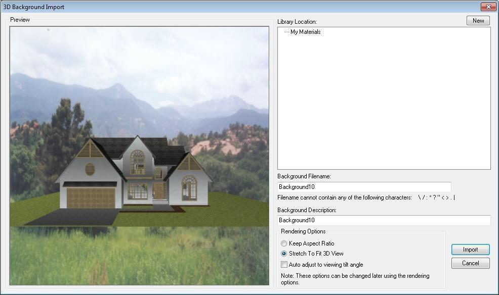
- Library Location specifies where you want to import the background image. You can choose an existing User Library category or sub-category or click the New button to create a new User Library category or sub-category.
- Background Filename and Background Description define the name and description of the material. New material descriptions can contain up to 78 characters.
- Rendering Options allow you to choose Keep Aspect Ratio to maintain the image size regardless of the 3D window size or choose Stretch To Fit 3D View to resize the image depending on the size of the 3D view window.
- Auto adjust to viewing tilt angle checkbox adjusts the background as the 3D view is tilted.
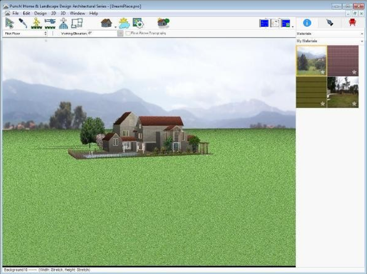
3- Click OK. The background is visible in the 3D view and is displayed in the Preview Bar, in the library that was selected. To apply a background, drag-and-drag the material onto the background in the 3D view.
Editing Materials
The Material Editor is a powerful tool that gives you control over the look of all of the materials that are available. You can edit the orientation and color properties of materials to adjust how they appear in the 3D view. Adjustment options include editing RGB values, Hue, Saturation, Brightness, Shadows, Midtones, Highlights, and Gamma Correction. The original preview is displayed in the top right corner. Changes you make are displayed in the large preview.
To edit a material, you must save a copy to the User Library. You can do this before you edit the material or save a copy directly from the Material Editor window after you've made your edits.
For information on the User Library, see “Organizing Library Content”
For information on applying materials, see “Applying Building Materials”
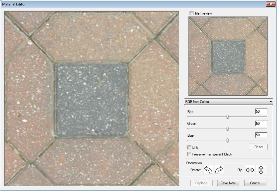
Tile Preview checkbox lets you tile the image in a 3x3 grid. When deselected, the image is a 1x1 stretched image.
You can choose to adjust the colors using the following methods. To adjust, drag the sliders or enter a value in the corresponding text box. To adjust all of the settings together, select the Link checkbox.
- RGB from Colors Adjust the Red, Green, and Blue settings based on the original colors
- RGB from Grayscale Adjust the Red, Green, and Blue settings based on a grayscale version of the material
- HSB from Colors Adjust the Hue, Saturation, and Brightness settings based on the original colors
- HSB from Grayscale Adjust the Hue, Saturation, and Brightness settings based on a grayscale version of the material
- Shadows/Midtones/Highlights Adjust the highlights, midtones, and shadows to provide smooth tonal transitions
- Gamma Correction Allows you to adjust the Red, Green, and Blue values to adjust the on-screen colors.
Reset button resets the settings to default.
Preserve Transparent Black checkbox allows you to display areas of pure black (RGB 0,0,0) as transparent.
Orientation buttons let you rotate or flip the material to adjust its position.
Replace button is available when you are editing a material that is saved in your User Library. This allows you to replace the existing material with any changes you make.
Save New button opens the Save New Material window, where you can choose the User Library where you want to save the material.
Cancel button closes the Material Editor and discards any changes.
To edit a material
-
Right-click a material in the Preview Bar and choose Edit Material.
-
Edit the material appearance as needed and then click Replace to update the material in a User Library or click Save New to save a new copy to the User Library.
Using the SmartWand
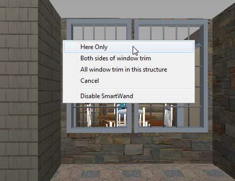
You can easily apply the same material, paint, or trim to multiple surfaces using SmartWand. SmartWand can be applied to walls, ceilings, doors, stairs, cabinets, and other surfaces in the 3D view. We will use “Paint” in this example, but SmartWand is used in the same way regardless of what you are applying.
To apply using SmartWand, drag-and-drop the item you want from the Preview Bar onto a surface in the 3D view window. The SmartWand menu lists all of the available options for the surface you’re applying to. Typically, this includes the option to apply to the individual surface only, or other similar surfaces in the room (or structure). Choose the surface or surfaces where you want it applied. The material is applied based on your selection.
For information on applying trim, paint, and materials, see:
- “Applying Trims”.
- “Applying Paint and Color”.
- “Applying Building Materials”.
To enable or disable SmartWand
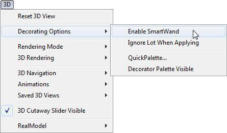
Click 3D menu > Decorating Options > Enable SmartWand. SmartWand is enabled when a checkmark is visible and disabled when no checkmark is visible.
(alternatively) Click Design menu > Options and under 3D Preferences choose General. You can select the Enable SmartWand checkbox to enable or deselect to disable. Click OK to close the window.
Working with QuickPalettes
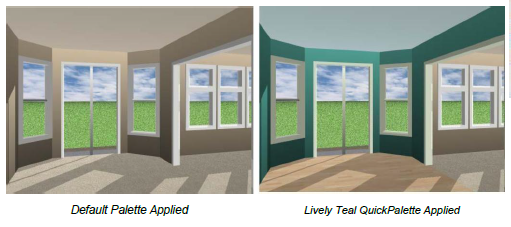
As you draw, default colors and materials are applied to the surfaces in your drawing. With FloorPlan Home & Landscape Software you can control the default colors and materials that are applied using QuickPalettes.
QuickPalettes are a collection of colors and materials that are designated for the surfaces in your drawing. When a Quickpalette is active, all of the surfaces are created using the colors and materials of that QuickPalette. You can also apply one of the QuickPalette designs to update the surfaces in your drawing all at once, allowing you to experiment with different looks and update entire rooms with just a few mouse clicks. After a QuickPalettes is applied to an entire room, you can update individual surface using the finishes in a QuickPalette by applying them to only a particular surface in the room.
QuickPalettes are controlled in the QuickPalette dialog box, where you can specify the default QuicPalette to be used for subsequent rooms, edit the materials and colors of each QuickPalette, and create new QuickPalettes. For more information, see "Editing QuickPalettes". (See below)
To apply a QuickPalette to a room
-
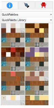
Click the Libraries tab and choose QuickPalettes from the Libraries drop-down menu. The QuickPalettes are displayed in the Preview Bar.
-
Drag-and-drop a QuickPalette onto a surface where you want it applied. If SmartWand is disabled, the QuickPalette is applied.
If SmartWand is enabled, the SmartWand menu is displayed, with the option to apply the QuickPalette to only that surface, or to all of the surfaces in entire room.
3- Click to apply QuickPalette to the surface(s) you want. The design is updated based on the QuickPalette.
Note: If a QuickPalette is applied to an exterior element, each surface is updated individually.
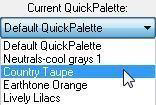
To change the default QuickPalette for drawing
-
Click 3D menu > Decorating Options > QuickPalette to open the QuickPalette dialog box.
-
From the Current QuickPalette drop-down menu, click the palette you want to use for subsequent surfaces in your drawing.
-
Close the QuickPalette dialog box. As you draw, the surfaces are finished based on the active QuickPalette you’ve specified.
Editing QuickPalettes
You can edit QuickPalettes to customize the materials and colors that are used for each surface. You can also create new QuickPalettes, rename existing QuickPalettes, and delete QuickPalettes (you cannot delete the Default QuickPalette). These edits are made in the QuickPalette dialog box
In the example below, the Automatic Room Flooring material is selected in the QuickPalette dialog box, and the material’s original library is displayed in the Preview Bar.
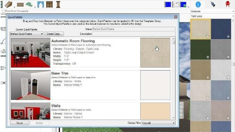
The red surfaces in the 3D previews show exactly where each material or color is applied. You can edit the material or color associated with each surface by applying a different material or color from the Preview Bar onto the preview in the QuickPalette dialog box.
Note: For more information on finding paint and colors, see “Applying Paint and Color”
For more information on finding paint and colors, see “Applying Building Materials”
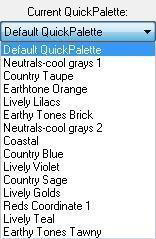
To see the surface materials and colors for each palette, choose a different palette from the Current QuickPalette drop-down menu. The Current QuickPalette is used to apply colors and materials to subsequent items in your drawing.
You can rename a QuickPalette or edit its description by typing new text in the Name and Description text boxes. For even more flexibility, you can create new QuickPalettes by copying an existing QuickPalette and editing the surface materials and colors.
You can even filter your view based on the surface you want to edit using the Display Filter drop-down menu at the bottom of the window.
To access the QuickPalette dialog box
-
Click the Libraries tab and choose QuickPalettes from the Libraries drop-down menu.
-
Click the QuickPalette Library drop-down menu and click Edit QuickPalettes. The QuickPalette dialog box is displayed. To close the dialog box, click the X in the top right corner.
(alternatively) Click 3D menu > Decorating Options > QuickPalette.
To customize a QuickPalette
-
Open the QuickPalette dialog box and then click the Current QuickPalette drop-down menu
-
and choose the QuickPalette you want to edit. The palette is displayed. Adding a Visual Array
-
Click the material or color preview that is associated with the surface you want to change. That color or material is displayed in the Preview Bar.
-
Find the color or material you want to use and drag-and-drop it onto the QuickPalette surface material or color you want to customize. The surface is updated.
-
Close the QuickPalette dialog box.
To create a new QuickPalette
-
Open the QuickPalette dialog box, as previously explained and open the QuickPalette you want to use as a starting point for your new QuickPalette from Current QuickPalette drop-down menu
-
Click the Create Copy button. The Copy QuickPalette dialog box is displayed.
-
Type a name and a description for the custom palette to add details about this palette and then click OK. The new palette becomes active in the QuickPalette dialog box. You can now customize QuickPalette and apply it to your design.
Note: You can change the name and description later while a palette is active in the QuickPalette dialog box.
To rename a QuickPalette
Note: You cannot rename the Default QuickPalette.
-
Open the QuickPalette dialog box and then choose the QuickPalette you want to edit from the Current QuickPalette drop-down menu. The palette is displayed.
-
Type a new name in the Name text box and then close the dialog box.
(optional) Type a description in the Description field to add details about this palette.
To delete a QuickPalette
Note: You cannot delete the Default QuickPalette.
-
Open the QuickPalette dialog box and then choose the QuickPalette you want to edit from the Current QuickPalette drop-down menu. The palette is displayed.
-
Click the Delete button at the bottom of the dialog box and then click Yes to confirm that you want to delete the palette and then close the dialog box.
Adding a Visual Array
The Visual Array Tool makes it easy to add a line of plants or 3D objects. From lining a path with plants, to edging a flowerbed with lights, you can enhance your plan with just a few clicks. In this example we will use plants, but the steps are the same for any other element.
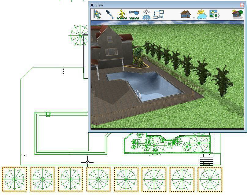
When the Visual Array Tool is active, the Spacing properties become available on the Properties tab. You should specify the distance you want between each item in the array and whether that distance is measure as the gap between the items or measure from the center of each item.
- Gap Between spacing distance is measured from the ends of each plant or object
- Center to Center spacing the distance is measured from the centers of each plant or object
You should be familiar with the plant and 3D object libraries and adding plants and 3D objects to your design. For more information, see:
- “Plants Libraries”
- “3D Objects Libraries”
To add a line of plants

-
Open the desired Plant or 3D object library and click to select the plant or object you want to add to your design.
-
On the Edit Toolbar, click the Visual Array Tool. The Properties tab is displayed with tool options.
-
Type the distance you want between each plant and choose how you want the spacing measure. Press ENTER to accept each new value.
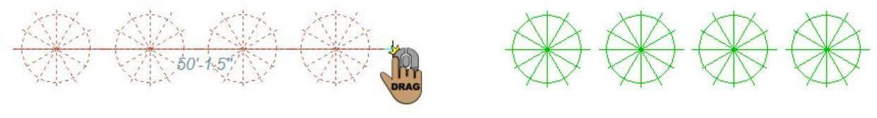
-
In the design window, click once to set the first point of the array, then drag your cursor in the direction you want. As you drag, the footprint of each object is displayed.
-
When you reach the length you want, click again to end drawing mode. The objects are placed in a line, at the spacing you defined.
Building Rooms Using Templates
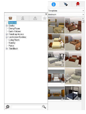
FloorPlan Home & Landscape Software includes dozens of room templates, which will make designing your home easy and fun. Divided into several categories, choose the template that suits your needs best.
To place a template
-
Click the Libraries tab and choose Templates from the Libraries drop-down menu. The Templates categories drop-down menu becomes available.
-
Click the Categories drop-down menu and choose the Library tab and category you want to view. Its contents are displayed in the Preview Bar.
Some of the categories are organized into sub-categories. Click to expand a category to see its contents.
3- Scroll through the available templates and drag-and-drop the template you want to onto the design window.
(optional) Click the Selection Tool and then click and drag the template you just placed into position.
Creating New Templates
With FloorPlan Home & Landscape Software you can easily create room templates to suit your specific needs. When you create a template, it is saved to the User Library. If you do not have a User Library folder created for Templates, you can create a new folder when saving the template. For more information on working with the libraries, see “Organizing Library Content”
Note: The 3D Preview option is only available when a 3D view window is open at the time of creating the new template. The 3D view should be so the objects in the template are visible.
To create a template
-
Once your room is designed exactly to your liking, select all walls, doors, and other features that you want to include in your template.
-
Click the Libraries tab and choose Templates from the Libraries drop-down menu. The Templates categories drop-down menu becomes available.
-
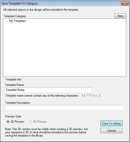
Click the Categories drop-down menu and, at the bottom of the menu, click the Options button and choose Create Template. The Save Template to Category dialog box is displayed.
-
Click to choose the Template Category or sub-category. You can choose an existing User Library category or sub-category or click the New button to create a new User Library category or sub-category.
-
Type a Template Name in the corresponding text box.
(optional) Type a Template Description in the corresponding text box. (optional) Choose the Preview Style you want to save.
6- Click Save To Library. The template is added to that User Library category and displayed in the Preview Bar.