Viewing in 2D & 3D
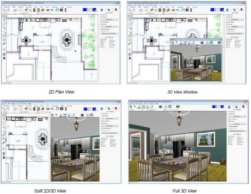
FloorPlan Home & Landscape Design Software provides many options for looking at your design on-screen. This gives you the flexibility to view your drawing as a 2D plan, in Elevation view, as a 2D plan with a corresponding 3D view, or using only Full 3D View.
When viewing your 2D home plan, you can magnify the view by zooming in, reduce the view by zooming out, or pan the view in any direction.
3D viewing provides many options, from walking through the home plan to flying around the plan or viewing the framing or completion phase of your project. You can adjust 3D display settings using a variety of viewing features, including adding shadows, for a realistic effect, or adjusting the lighting intensity of the view. Finally, you can create a photo-realistic view of your design.
In this chapter, you’ll learn about the numerous commands designed to let you view your design in both 2D and 3D.
Viewing the 2D Plan
When initially designing your plan, you will probably want to view the 2D plan view only. Once completed, you can view your plan in a combination of 2D and 3D or in 3D only. In addition, FloorPlan Home & Landscape Design Software organizes your floor plan into layers, which are each easily accessible with a single mouse click. For example, you can choose to view the deck plan with landscaping one moment, then quickly switch to view electrical and plumbing. Any combination any time!
To view the 2D plan only 
- On the View Toolbar, click the 2D Plan View icon. The 2D plan view is
displayed. (alternatively) Click Window menu > 2D Plan View.
To view all 2D floor plan levels at once 
- Click the Working Floor button at the left bottom of the design window, then click to check View All Floors.
To view the working floor only
- Click the Working Floor button at the left bottom of the design window, then click to check View Working Floor Only.
Customizing Visible Plans
During the design of your floor plan, there may be times when you want to view certain layers that are hidden by default. For example, while working on your electrical plan, you may need to see where plumbing will be. FloorPlan Home & Landscape Design Software makes it easy to customize how you view your plan layers. The visible plans are controlled on the Properties tab under Plan and Editing.
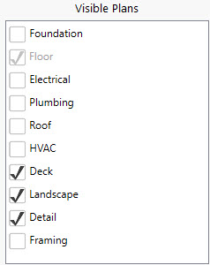
Note: Items on a hidden plan layer are not available during a Select All process and will not be altered with the other items and features in your drawing.
You can also assign custom colors to areas of your design, such as plans,
inactive floors, grid line colors, and the color of your crosshair. These color settings, and more, can be customized by accessing the 2D menu.
To customize plan layers
-
Click the plan tab you want to use, and then make sure nothing is selected in the 2D or 3D views and click the Properties tab. The Plan and Editing settings are displayed.
-
Select the plan(s) you want to be visible in the design window or deselect the plan(s) you want to hide.
Show Topography Lines
There may be times when you will want to work on the Landscape Plan, but you may want to hide the topography lines. This is a one-click procedure. Topography lines are displayed when the Landscape plan tab is enabled, but you have the option to display or hide the topography lines.
To control topography lines visibility
- Click 2D menu > Show Topography Lines. If there is a checkmark next to this menu selection, it is active. If there is not a checkmark next to this menu selection, it is inactive.
Zooming In and Out in 2D
You can get a closer look at an area or see a larger portion of your plan drawing by zooming in and out. By dragging over the drawing, the view enlarges or decreases dynamically. You can also set the zoom factor to obtain exact zoom precision. Once you’ve finished viewing your plan close-up, you can return to the previous, full view with one mouse click.
To zoom in
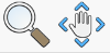
- On the main toolbar, click the Zoom Tool.
- Click on the design window and drag up to zoom in; drag down to zoom out
(alternatively) Zoom in and out easily with the wheel on your mouse.
Note: The location of the cursor will be centered on the design window.
To set the zoom factor
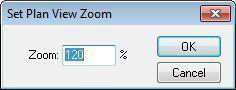
- Click 2D menu > Set Zoom. The Set Plan View Zoom dialog box is displayed.
-
Type a new zoom factor, then click OK. To reset the 2D plan view
-
Click 2D menu > Reset Plan View (or press CTRL+E). Your plan is reset to the original, default view.
Panning Across the 2D Drawing
You can move the design window to see portions of the plan which are outside the current view, by panning. Panning also makes it easy to slowly view areas of your drawing piece-by-piece.
To pan in any direction
- On the main toolbar, click the Pan Tool. The pointer changes to reflect Pan mode.
- Hold down the left mouse button and drag in the direction you want to view. The view changes, dynamically, as you move the mouse.
(optional) With some mice you can hold down the wheel on your mouse and move in it the direction you want to pan.
Fitting Your Design to Your Current Window Size and Selection
You can quickly position your entire design within your window, without using the Pan Tool or Zoom Tool.
To fit your entire design within your window
- Click 2D menu > Fit to Window (or press CTRL+F).
To fit your entire design within your window
- Click 2D menu > Fit to Selected or use the 2D View Bar (right bottom corner of the screen)
Sheet Layout mode
Setting up a layout
When in FloorPlan Home Design mode click on the Sheet Layout Mode button to enter Layout Mode. If the layout has not been setup yet you will get the setup screens. Setup your paper size and add pages.
Layout mode is designed to print toscale on the same size paper as is set when creating the layout sheets. Marginswill also need to match the target printer. It’s recommended that the papersize and print margins be known before starting a layout however there is anoption to automatically adjust the layout elements when changing paper size.
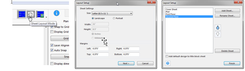
A title block page is automatically added for the user.The Add default design to title block sheet option will insert the defaulttitle block design for the user.
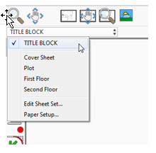
You can access the sheet set and page setup dialogs fromthe active sheet list.
Title Block Sheet
The title block sheet is where you want to draw any borders, add company or customer information. Elements drawn on the title block page will be drawn on all layout sheets but only editable on when on the title block sheet.
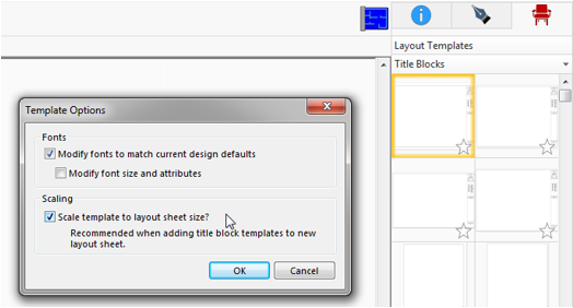
TitleBlock Template
Title block templates are included. There are multiple options available, each one optimized for certain paper sizes.When dragging a template on to the page choose the “Scale template to layout sheet size” option to automatically scale the title block to your sheet margins.
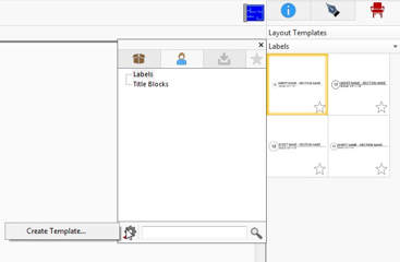
Additional layout templates can be created by selecting the desired objects and choosing Create Templates from the options button in the template navigation window.
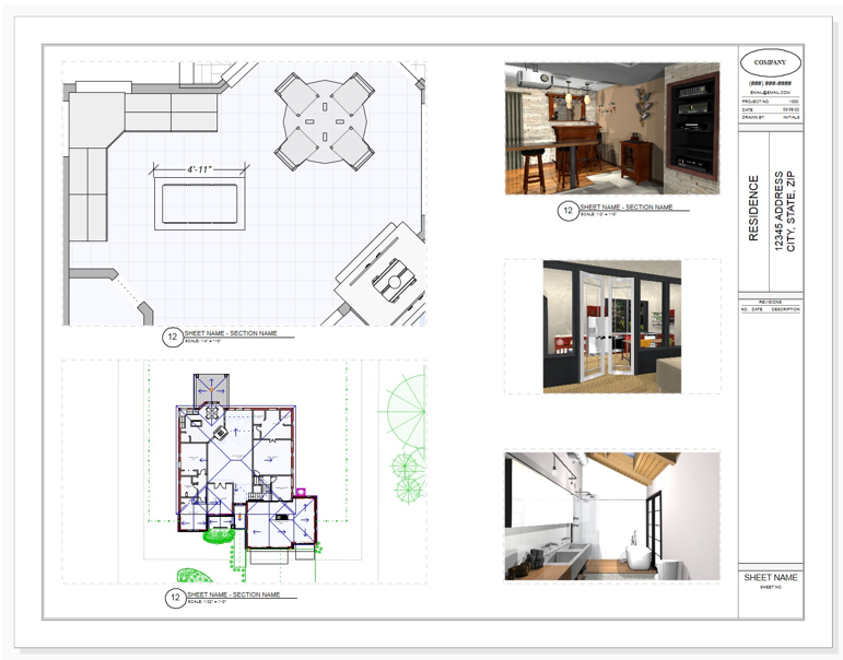
Creating views in Layout Mode
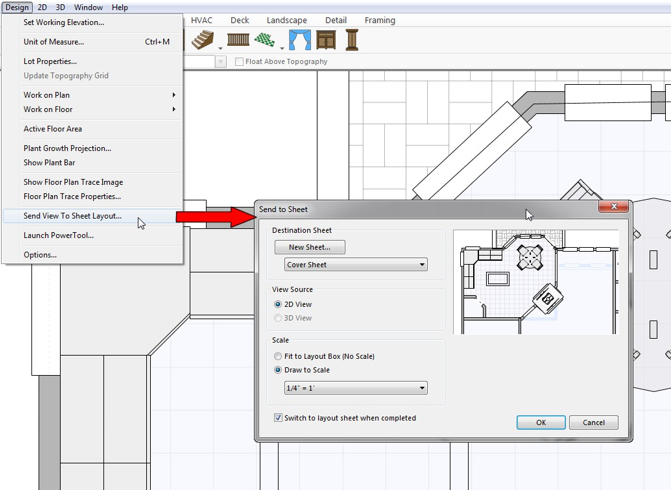 |
Layout views can be created manually in Layout Mode or when in home design mode use the menu command Design > Send View To Layout Sheet.
Send to Sheet Options:
· If the 3D window is visible, you can also send the current 3D view after saving it to a file.
· Scale options:
o Fit to layout box: Maintains current view from Home Design Mode and is not drawn at a scale.
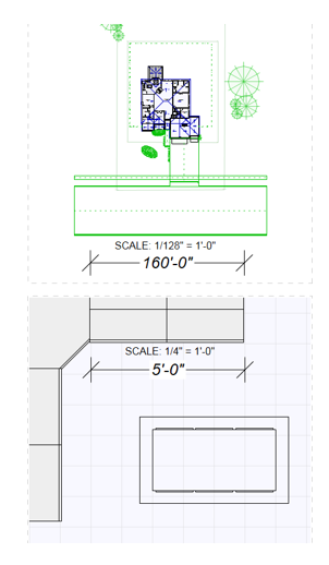
o Draw to Scale: When draw to scale options is chosen the view in Layout mode may look different but the view will be centered in the layout view. Setting a new scale or other adjustments may be necessary depending on the sheet’s paper size. If the paper size is small a smaller scale may be needed to fit desired drawing elements into the view.
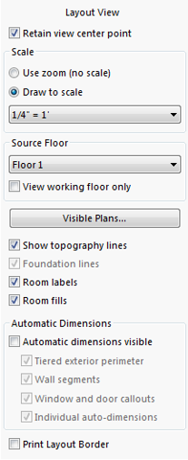
Layout View Options and Editing
Select a layout view object to display the properties sheet. Many options to control what are displayed inside a view can be found here.
· Retain view center point:Controls how the view is adjustedwhen modifying the size of a layout view.
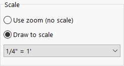
· Scale: Allows sheet to zoom in different scales. Use zoom will give the drawing in default or custom scale.Draw to scale option allows you to set layout drawing to different given scales.
· Source Floor: You can switch to different floors by this option. Enabling Working floor only enables walls and 3D object traces of different floors.
· Visible Plans: Button allows you to enable/disable different plan tools in Layout mode.
· Topography,Foundation lines, Room Labels and Room fills can be enabled/disabled by those given check-boxes.
· Dimension of the layout drawing can be enabled/disabled by those given check-boxes.
· Print Layout Border: By default,borders of views are dashed light lines and are not printed. With this option turned on the border will be printed. The properties of the border can be adjusted on the draw style tab.
·  The standard pan and zoom tools edit the view of the entire sheet.
· Use the layout view edit tools to modify a layout’s center or zoom. 
o Using the Control key will allow you to pan the layout view with by pressing the mouse wheel or with the standard pan and zoom tools.
· Dimension lines drawn in layout mode have optional scale settings. Automatic option will use the scale of the layout view the dimension is drawn on. The same sized dimension drawn on different views will display different measurements.
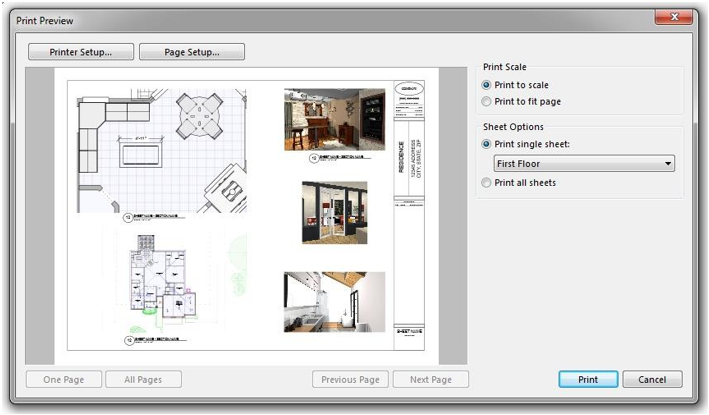
Printing
Layout mode is designed to print to scale on the same size paper as is set when creating the layout sheets. If trying to print on a different size paper the fit to page option will need to active and the layout will not be printed to scale.
Options to print individual pages or all sheets (title block page not included).
Working with 3D Views
FloorPlan Home & Landscape Design Software lets you view your design in photo-realistic 3D. You can select the exterior and interior wall colors, add realistic roof materials, and select from a variety of textures to make your design completely unique. In the 3D View Window, you can view your design from a variety of angles.
Using Decorator Palettes, you can easily make changes to your decorating theme. This makes it easy to experiment with a variety of color schemes, both inside and outside your design, before picking up a paintbrush!
With the powerful ClearView feature, you can literally see through the walls and view electrical, plumbing, and so on.
All 3D View window options are easily accessible from the right-click context menu, the View toolset in the main toolbar, and from the 3D menu.
To refresh your 3D view
Click 2D menu > Refresh (or Press F5).
To display plan view
- Click the Plan View icon on the main toolbar.
(alternatively) Click Window menu > 2D Plan View.
(alternatively) Right-click, while nothing is selected, and click Plan View from the pop- up menu that is displayed.
To display the 3D View Window
- Click the 3D View Window icon from the collapsible view toolset. (alternatively) Click Window menu > 3D View Window. (alternatively) Right-click, while nothing is selected, and click 3D View Window from the context menu that is displayed.
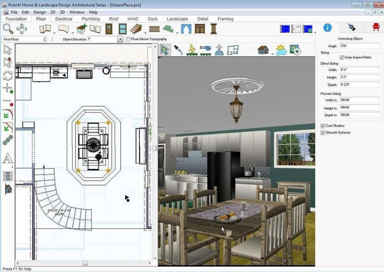
To display a split 2D/3D view
- Click the Split 2D/3D View icon from the collapsible view toolset. (alternatively) Click Window menu > Split 2D/3D View. (alternatively) Right-click, while nothing is selected, and click Split Plan/3D View from the context menu that is displayed.
To display full 3D view 
- Click the 3D Full View icon from the collapsible view toolset. (alternatively) Click Window menu > 3D Full View. (alternatively) Right-click, while nothing is selected, and click 3D Full View from the context menu that is displayed.
To display elevation view
- Click the Elevation View icon from the collapsible view toolset. (alternatively) Click Window menu > Elevation View. (alternatively) Right-click, while nothing is selected, and click Elevation View from the context menu that is displayed.
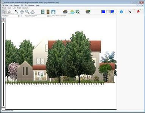
There are predefined views available in the toolbar. Choose one of the views to quickly see your design from that direction, or click the Rotate Elevation View Angle Tool and drag in the view window to rotate around the design.
You can add doors, windows, and accessories while in Elevation View by selecting one of the tools and then clicking on a wall to place.
While in Elevation View, you can also edit roofs, decks, and 3D objects that exist in your design.
Using 3D Cutaway
With FloorPlan Home & Landscape Design Software’s 3D Cutaway Tool you peel away layers of your floor plan, with ease. You can slice away layer after layer of your design from nearly any angle, making it easy to see room arrangements, furniture placement, and more. You can add as many cutaway lines as you’d like, but only one can be active at a time.
The 3D Cutaway Tool is available from the Edit Toolbar and is placed in the design window where you define the length and angle of the cutaway line. There are three directions you can cutaway, which are available on the Properties tab when either the tool is active or a cutaway line is selected.
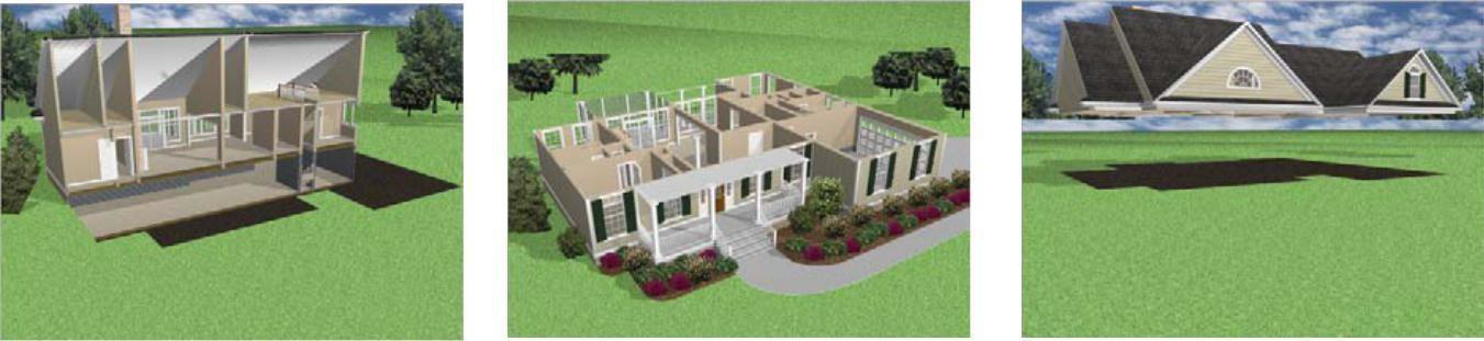
Vertical Horizontal From Top Horizontal From Bottom
Cutaway Vertically
The vertical direction gives you a doll house view of your design, allowing you to see inside. When the vertical direction is active, arrows are displayed on the cutaway line showing you the direction you are cutting away. You can flip the direction easily on the Properties tab.
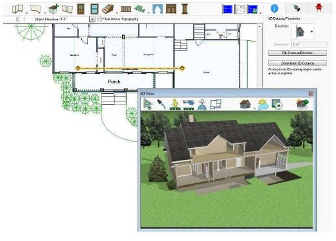
In this example the cutaway line is placed at the front of the house and is pointing towards the back
To place a vertical cutaway
-
On the Edit toolbar, click the 3D Cutaway Tool.
-
On the Properties tab, click the Direction drop-down menu and choose Vertical.
-
Use the Click-and-Drag drawing method to drag the cutaway line to the length and angle you want. Once placed, you can drag the line to a new position to adjust the cutaway.
(optional) Click the Flip Cutaway Direction button to choose which direction is cutaway. The arrows on the endpoints of the cutaway line point towards the direction being cutaway.
4- Open a 3D view and navigate so you can see your design.To control a cutaway display
5- Select the cutaway line you want to activate or deactivate.
6- On the Properties tab, click Deactivate 3D Cutaway to disable it or Activate 3D Cutaway to enable it.
(alternatively) Right-click the cutaway line and choose Deactivate 3D Cutaway to disable it or Activate 3D Cutaway to enable it.
To view the cutaway in Elevation View
- Right-click the cutaway line and choose Display Cutaway in Elevation View.
Cutaway Horizontally
You can cutaway horizontally from the top or the bottom of your design. When one of the horizontal cutaway directions is active, you can set the elevation for the cutaway line to control how much of your design is cutaway. The elevation is an absolute measurement from 0 rather than relative to the top or bottom of your design. For example, if your cutaway elevation is 8'-0", your design is cutaway from the top down to 8'-0", or from the bottom up to 8'-0".
When placing a cutaway line to cutaway the top or bottom of your design, the length and direction of the line are not important because the cutaway plane is based on the elevation of the line rather than the angle or length.
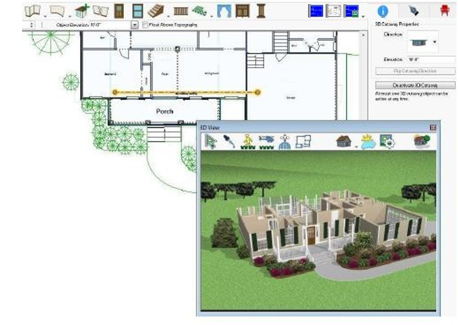
In this example the cutaway line is placed at an elevation of 10'-0" and cutting away from the top of the home
To place a horizontal cutaway

- On the Edit toolbar, click the 3D Cutaway Tool.
- On the Properties tab, click the Direction drop-down menu and choose From Top or From Bottom.
- Use the Click-and-Drag drawing method to drag the cutaway line to the length and angle you want. Once placed, you can drag the line to a new position to adjust the cutaway.
- Type the elevation you want for the cutaway line and press the ENTER key.
- Open a 3D view and navigate so you can see your design.
To control a cutaway display
- Select the cutaway line you want to activate or deactivate.
- On the Properties tab, click Deactivate 3D Cutaway to disable it or Activate 3D Cutaway to enable it.
(alternatively) Right-click the cutaway line and choose Deactivate 3D Cutaway to disable it or Activate 3D Cutaway to enable it.
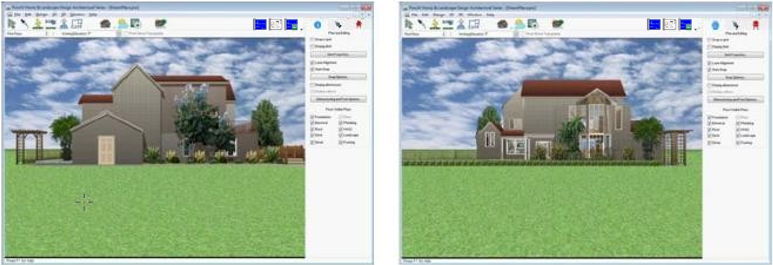
Setting the Walk-Through Viewpoint Angle
FloorPlan Home & Landscape Design Software has four pre-set viewpoint angles and, from those angles, moving to the needed viewpoint is easy. Below is example of the Right View. By clicking the other three directions, you can view your floor plan from the other edges of your lot.
To set a viewpoint angle
- Click the Full 3D View icon from the collapsible view toolset.
- Click 3D menu > 3D Navigation and choose Front View, Back View, Right View, or Left View.
Selecting Features in 3D
With FloorPlan Home & Landscape Design Software’s 3D Selection Tool, you can click features on the 3D View window and they are automatically selected on your 2D plan. This makes fine-tuning your design much easier. For example, you can easily select windows that may be stacked on top of each other in the 2D design view.
In the image below, we’ve selected the table in the 3D View window.
Note: You can select features on the active floor and active plan only. If the feature you click does not become active, make sure it is on the active floor and plan.
To use the 3D selection tool
- Open a 3D window and click the Select Objects in 3D Tool.
- In the 3D View window, click a feature to select it. The feature is selected in the design window and its properties are displayed on the Properties tab.