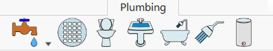
Plumbing Plan Tab
Once you’ve completed your floor plan, the next step in the design process is to plan your utilities. FlooPlan Home & Landscape Software features a suite of plumbing fixtures from basic toilets to spa tubs. Other important considerations are gas bibs and floor drain placement, also included in FlooPlan Home & Landscape Software. Most plumbing components are designed to “track the walls”, meaning they can only be placed on wall segments to offer flawless design. Tubs and showers are automatically annotated and dimensions appear, as you add plumbing, to ensure accurate placement. Each plumbing component is simple to include in your drawing, with the flexibility to modify it at any time.
Placing an Outdoor Hose Bib or Gas Bib
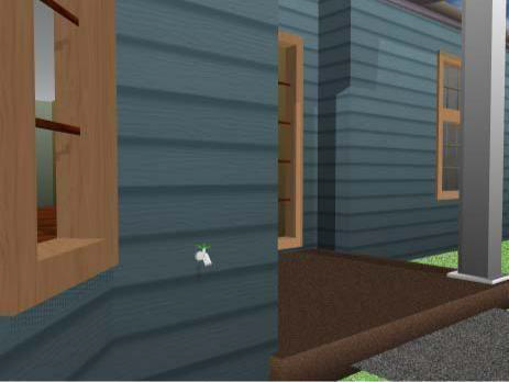
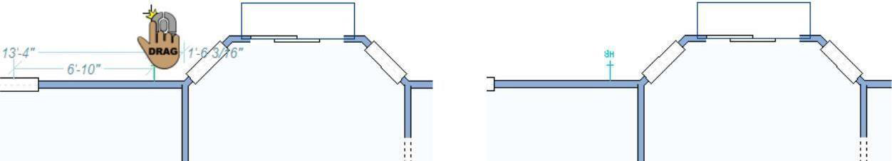
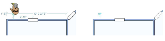
When you place an outdoor hose bib or a gas bib, dimension lines automatically appear, making it easy to place objects a specific distance from a neighboring plumbing fixture or the end of a wall segment. You’ll notice that when placing hose bibs, the object is automatically “tracked” to the wall segment, making accurate placement simple. As you drag to position the bib, dimension lines indicate the distance from the center of the bib to the nearest wall end or plumbing fixture.
The following tools are available from the Bib toolset.
Below are some references that may be helpful as you design:
- AutoSnap and Alignment Options
- Elevating Objects
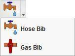
To place a hose bib 
- On the Plumbing plan toolbar, click the Hose Bib Tool from the Bib toolset.
- Use the Drag Along Wall drawing method to position the bib on the side of a wall where you want it and release to place.
To place a gas bib
1- On the Plumbing plan toolbar, click the Gas Bib toolset.
2- Use the Drag along wall drawing method to position the bib on the side of a wall there you want it and release to place
Adding Floor Drains
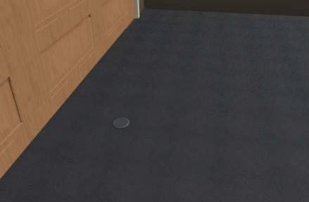
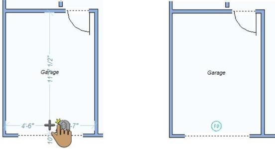
Once you’ve completed your plumbing plan, the final step is to add floor drains to your design. Adding floor drains is as simple as a mouse click.
Below are some references that may be helpful as you design:
- Elevating Objects
- Moving a Selection
- Nudging a Selection
To add a floor drain 
- On the Plumbing plan toolbar, click the Floor Drain Tool.
- Use the Click Once to Place drawing method to place the floor drain in your design.
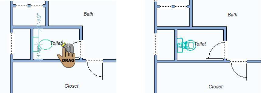
Placing Toilets
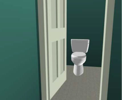
FlooPlan Home & Landscape Software makes it simple to add plumbing to your home plan. Dimension lines automatically appear, making it easy to place objects a specific distance from a neighboring plumbing fixture or wall segment. You’ll notice that, when placing toilets, the object is automatically “tracked” to the wall segment, making accurate placement simple.
When the tool is active you can choose the style, you want from the Properties tab. You can also change the style after the toilet has been placed by selecting the toilet in your drawing and choosing a different style.
Below are some references that may be helpful as you design:
- Toilet Properties
- AutoSnap and Alignment Options
- Elevating Objects
- Moving a Selection & Nudging a Selection
- Applying Building Materials & Applying Paint and Color
To place a toilet 
-
On the Plumbing plan toolbar, click the Toilet Tool.
-
Use the Drag Along Wall drawing method to position the toilet on the side of a wall where you want it and release to place.
Toilet Properties
Toilets are defined by their length, width, and how far they are offset from the wall. You can edit the properties after the object has been added to your design by selecting it and clicking the Properties tab.
Note: When editing values in a text box, be sure to press ENTER to accept changes.
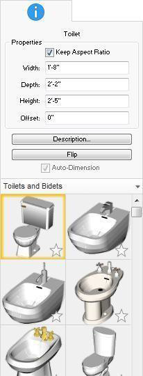
- Keep Aspect Ratio checkbox resizes the component proportionally when one of the dimensions is changed. When selected, the aspect ratio is maintained; when deselected, only the value you edit is changed.
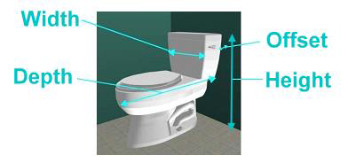
- Width defines the distance from one side of the toilet to the other side.
- Depth defines the distance from the back of the toilet to the front.
- Height defines the distance from the base of the toilet to the top.
- Offset defines the distance between the wall and the back of the toilet.
- Description button opens the Description dialog box. For more information on editing descriptions, see “Component Description”
- Flip button allows you to flip the side where the hardware is positioned.
- Styles library includes the available toilets and bidets styles. You can choose the style before or after you place the toilet.
Placing Sinks
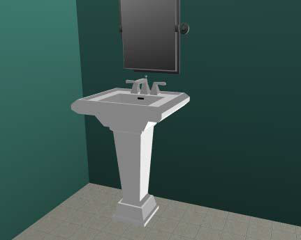
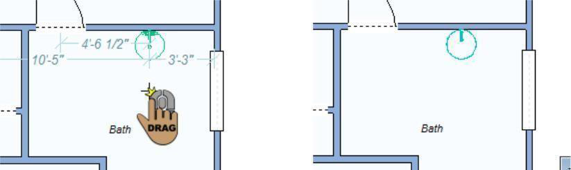
As with toilets, sinks are automatically tracked to wall segments, as you place them, as well as automatically dimensioned to neighboring walls and plumbing fixtures. As you drag along a wall, the dimension lines indicate the distance from the center of the sink to the nearest wall end or plumbing fixture.
When the tool is active you can choose a bathroom or kitchen sink style from the Properties tab. You can also change the style after the sink has been placed by selecting the sink in your drawing and choosing a different style.
Below are some references that may be helpful as you design:
- Sink Properties
- AutoSnap and Alignment Options
- Elevating Objects
- Moving a Selection & Nudging a Selection
- Applying Building Materials & Applying Paint and Color
To place a sink 
- On the Plumbing plan toolbar, click the Sink Tool.
- Use the Drag Along Wall drawing method to position the sink on the side of a wall where you want it and release to place.
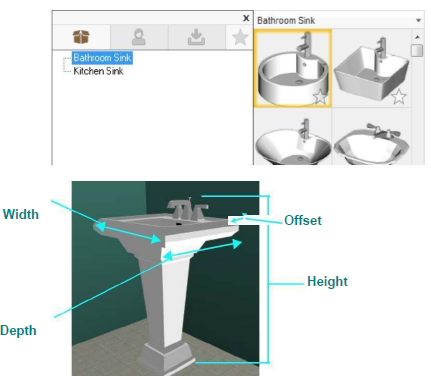
Sink Properties
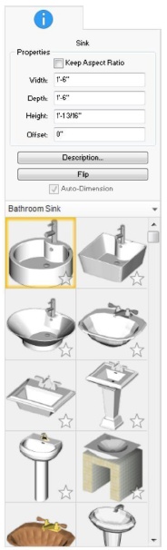
Sinks are defined by their length, width, and how far they are offset from the wall. You can edit the properties after the component has been added to your design by selecting it and clicking the Properties tab.
Note: When editing values, always press the ENTER key to accept new values in a text field.
- Keep Aspect Ratio checkbox resizes the component proportionally when one of the dimensions is changed. When selected, the aspect ratio is maintained; when deselected, only the value you edit is changed.
- Width defines the distance from one side of the sink to the other side.
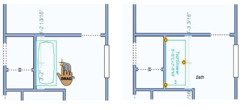
Placing Bath Tubs
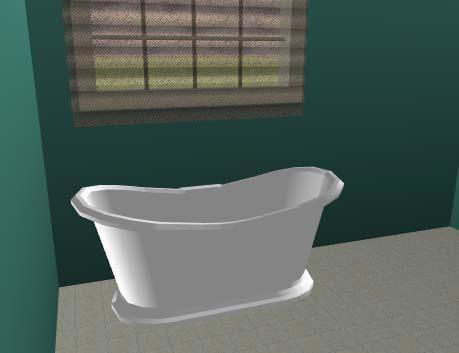
In addition to associative dimensioning and wall tracking as you place a tub, FlooPlan Home & Landscape Software automatically adds annotation to your design when the tub is placed. This makes reading home plans simple. If you don’t find the exact sized tub you are looking for, simply place a tub that is similar in size, then adjust the tub or spa properties to the exact size you want for your home design. As you drag along a wall, the dimension lines indicate the distance from the center of the sink to the nearest wall end or plumbing fixture.
When the tool is active you can choose a bath tub style from the Properties tab. You can also change the style after the bath tub has been placed by selecting the tub in your drawing and choosing a different style.
Below are some references that may be helpful as you design:
- Bath Tub Properties
- AutoSnap and Alignment Options
- Elevating Objects
- Moving a Selection & Nudging a Selection
- Applying Building Materials & Applying Paint and Color
To place a bath tub
1- On the Plumbing plan toolbar, click the Bath Tub Tool
2- Use the Drag Along Wall drawing method to position the bath tub on the side of a wall where you want it and release to plan
Bath Tub Properties
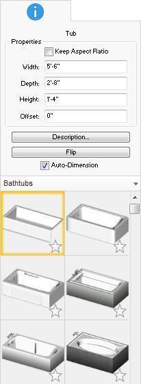
Bath Tubs are defined by their length, width, and how far they are offset from the wall. You can edit the properties after the component has been added to your design by selecting it and clicking the Properties tab.
Note: When editing values, always press the ENTER key to accept new values in a text field.
Keep Aspect Ratio checkbox resizes the component proportionally when one of the dimensions is changed. When selected, the aspect ratio is maintained; when deselected, only the value you edit is changed.
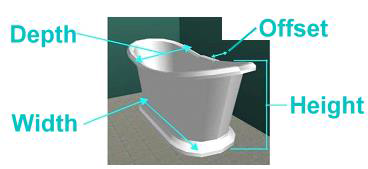
- Width defines the distance from one side of the tub to the other side.
- Depth defines the distance from the back of the tub (edge against the wall) to the front.
- Height defines the distance from the base of the tub to the top of the tub hardware.
- Offset defines the distance between the wall and the back of the tub.
- Description button opens the Description dialog box. For more information on editing descriptions, see “Component Description”
- Flip allows you to flip the side where the hardware is positioned.
- Auto-Dimension checkbox controls the display of the tub dimensions. When selected, tub dimensions are displayed.
- Styles library includes the available bathtub styles. You can choose the style before or after you place the tub.
Placing a Shower
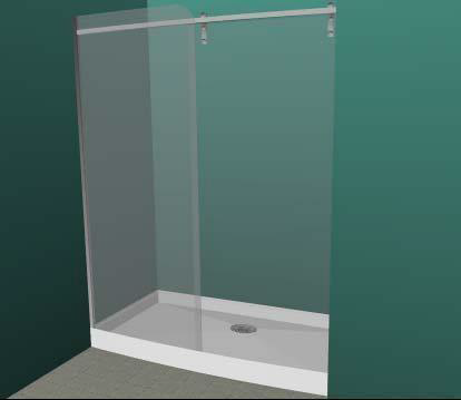
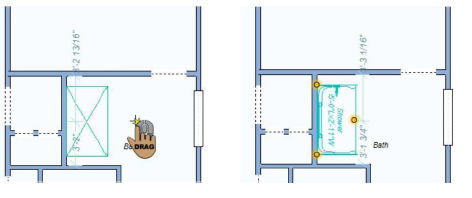
Showers are placed in the same manner as bath tubs. In addition to associative dimensioning and wall tracking, as you place a shower, FlooPlan Home & Landscape Software automatically adds annotation to your design once the shower is placed. If you don’t find the exact sized shower you are looking for, simply place a shower that is similar in size, then adjust the shower properties to the exact size you want for your home design. As you drag along a wall, the dimension lines indicate the distance from the center of the shower to the nearest wall end or plumbing fixture.
When the tool is active you can choose a shower style from the Properties tab. You can also change the style after the shower has been placed by selecting the shower in your drawing and choosing a different style.
Below are some references that may be helpful as you design:
- Shower Properties
- AutoSnap and Alignment Options
- Elevating Objects
- Moving a Selection & Nudging a Selection
- Applying Building Materials & Applying Paint and Color
To place a shower
1- On the Plumbing plan toolbar, click the shower Tool,
2- Use the Drag Along Wall drawing method to position the component on the side of a wall where you want it and released to place.
Shower Properties
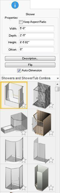
Showers are defined by their length, width, and how far they are offset from the wall. You can edit the properties after the component has been added to your design by selecting it and clicking the Properties tab.
Note: When editing values, always press the ENTER key to accept new values in a text box.
- Keep Aspect Ratio checkbox resizes the component proportionally when one of the dimensions is changed. When selected, the aspect ratio is maintained; when deselected, only the value you edit is changed.
- Width defines the distance from one side of the shower to the other side.
- Depth defines the distance from the back of the shower to the front.
- Height defines the distance from the base of the shower to the top.
- Offset defines the distance between the wall and the back of the shower.
- Description button opens the Description dialog box. For more information on editing descriptions, see “Component Description”
- Flip allows you to flip the side where the hardware is positioned.
- Auto-Dimension checkbox controls the display of the shower dimensions. When selected, shower dimensions are displayed.
- Styles library includes the available shower styles. You can choose the style before or after you place the shower.
Placing the Water Heater 
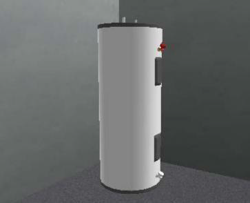
Adding a water heater to your home plan is as simple as a mouse click.
Dimensions are displayed as you move the cursor around the design window, which indicate the distance from the center of the object to the nearest wall or other component.
Below are some references that may be helpful as you design:
- AutoSnap and Alignment Options
- Elevating Objects
- Moving a Selection & Nudging a Selection
- Applying Building Materials & Applying Paint and Color
To place a water heater
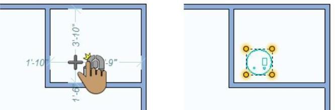
- On the Plumbing plan toolbar, click the Water Heater Tool.
- Use the Click Once to Place drawing method to place the water heater in your design.