Local Face Operations
Available in ViaCAD Pro)
Face operations tools allow you to manipulate individual object faces. These operations include:
- Push/pull (extrusions and protrusions)
- Draft
- Match
- Move
- Offset
- Remove
- Replace
- Parting Line
- Pattern
Push/Pull
The Push/Pull tool allows you to create 3D objects from 2D lines or curves by simply dragging to extrude an enclosed shape. This tool can also be used to resize 3D objects by dragging a face.
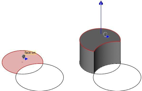
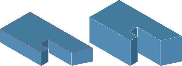
The Push/Pull tool detects lines or curves that exist on a face, so you can use the Push/Pull tool to extrude individual faces that are made up of enclosed lines and curves to create protrusions and holes within an object.
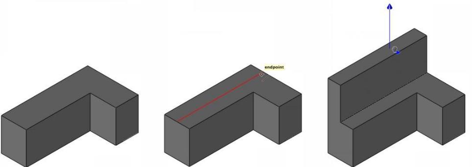
Extruded face created with a line
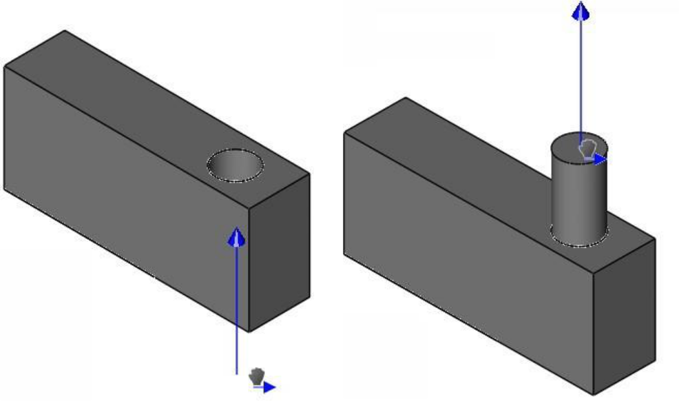
Protrusion created from circleHole created from circle
As you’re dragging, if the face you are pushing/pulling becomes co-planar with another existing face, the existing face appears highlighted so you know when the two faces are aligned. This makes pushing or pulling faces into alignment with existing faces very easy.
Using the Push/Pull tool to extrude individual faces on an object
- Draw a line, curve, or polygon to create an enclosed face within a larger object.
- Click the Push/Pull tool.
- Hold down your left mouse button and drag the face in the direction you want to push/pull.
- Release when the face is at the desired distance.
- (optional) Enter values in the Data Entry window to specify the distance.
Push/Pull of curves requires that the curves lie in the current Work Plane. For curves that do not lie in the Work Plane, you can set the Work Plane to the curves using the Work Plane: Select Objects.
Draft
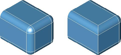
The Draft Face operation will rotate a collection of faces about an edge. The Draft Face tool will extend or re limit adjacent faces. The following terms are used when creating a drafted face.
Reference Face A face whose normal defines the draft angle. Sometimes this is referred to as the pull direction for molds.
Reference Edge A linear edge whose direction defines the draft angle.
Neutral Position A face whose normal defines the pull direction. Since this position doesn't change, it is called the neutral position.
Using the Draft tool
- Select the reference face for the draft angle.
- Select the faces to draft. Use Shift key for multiple faces.
- Specify the neutral point.
- Use the Data Entry Fields to change the draft angle.
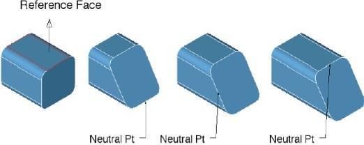
Draft Face
Match Face
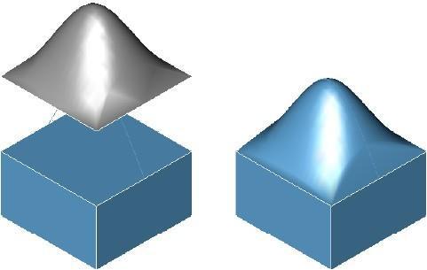
The Match Face command will modify the orientation and position of a selected face to that of a referenced face.
Using the Match Face tool (To Face)
- Select face to modify.
- Select the face to match.
- There are no Data Entry Fields entries for this command.
Match Face to Face
Using the Match Face tool (To Surface)
- Select face to modify.
- Select the surface to match.
- There are no Data Entry Fields entries for this command.
Match Face to Surface
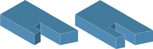
Move Face
The Move Face tool will translate one or more faces by a vector amount. Neighboring faces are extended or relimited to account for the new position.
Using the Move Face tool
- Select one or more faces to move.
- Specify two points for the move direction and magnitude.
- Use the Data Entry Fields to adjust the dx, dy, and dz components.
Move Faces
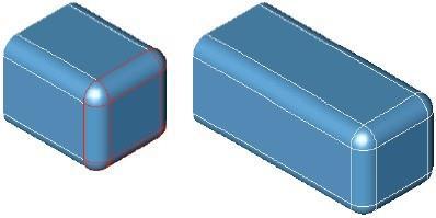
Offset Face
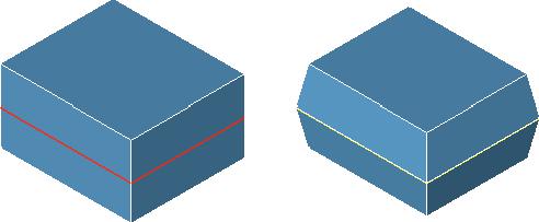
The Offset Face tool will offset one or more faces a positive or negative distance. Neighboring faces are relimited to the new offset face.
Using the Offset tool
-
Use the Data Entry Fields to specify an offset value.
-
Select one or more faces to offset. In the figure below, top face in red is offset upwards.

Offset Face
Offset Face
The Offset Face tool will offset one or more faces a positive or negative distance. Neighboring faces are relimited to the new offset face.
Using the Offset tool
- Use the Data Entry Fields to specify an offset value.
- Select one or more faces to offset. In the figure below, top face in red is offset upwards.
Offset Face
Remove Face
The Remove Face tool will delete one or more faces from a part. More than one face can be removed in one operation. Internally, neighboring faces are extended and relimited to account for the removed faces.
Using the Remove Face tool
- Select faces to remove. Hold the Shift key for multiple faces as in example below.
- There are no Data Entry Fields entries for this tool.
Remove Face
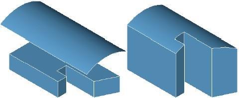
Replace Face
The Replace Face tool will substitute a new surface for the selected face. The surface must lie precisely along the edges of the face to replace.
Using the Replace tool
- Select the face to replace.
- Select the surface to replace with.
The example below shows the surface translated up for clarity. The surface must lie on the face edges that are being replaced.
Replace Face
Parting Line
The Parting Line tool will take a collection of curves that lie on a solid, imprint them onto the solid (creates split faces), and add draft to the upper and lower surfaces relative to the parting line.
Using the Parting Line tool
-
Select the part for the parting line operation.
-
Use the Data Entry fields to specify upper and lower draft.
-
Select the curves that lie on the solid for the parting line.
Pattern
Solid modeling often involves the repetition of features or objects arranged in a regular or irregular manner (copied or transformed), which may be referred to as patterns. Examples of patterns include the radial arrangement of holes in a shower head, the linear grating of ventilation holes on a computer monitor or the treads on a tire. Creating such patterns can become unnecessarily burdensome, especially when the number of repetitive elements grows large.
The Pattern tool reduces this burden by offering pattern types to facilitate pattern creation. The following eight patterns are available on the Data Entry window, once the tool is activated:
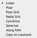
Linear
Creates a linear pattern specified by quantities along the x, y, and z axis. Spacing is controlled by the dX, dY, and dZ filed on the Data Entry window. Use the Hex option to stagger the rows to create a hexagon pattern.
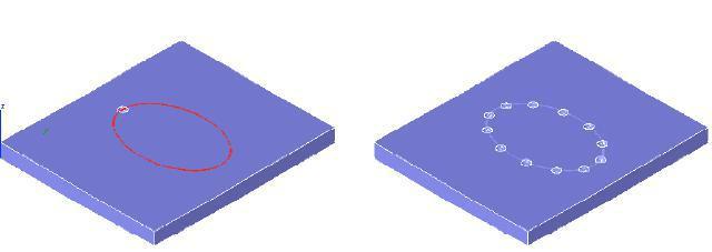
Polar
Creates a polar array pattern specified by the number of angles.
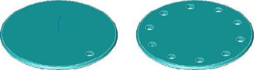
(a) Original(b) Polar Array
Polar Array Feature
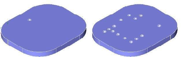
Polar Grid
Creates a polar grid pattern specified by the number of angles.
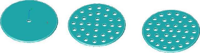
(a) Original(b) Polar Grid(c) Polar Grid Hexagon
Polar Grid Feature
Radial
Creates a radial pattern specified by the number of angles.
Cylindrical
Creates a cylindrical pattern specified by the number of angles.
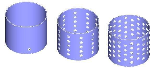
(a) Original(b) Cylindrical (c) Cylindrical Hexagon
Cylindrical Feature
Spherical
Creates a spherical pattern specified by the number of angles.
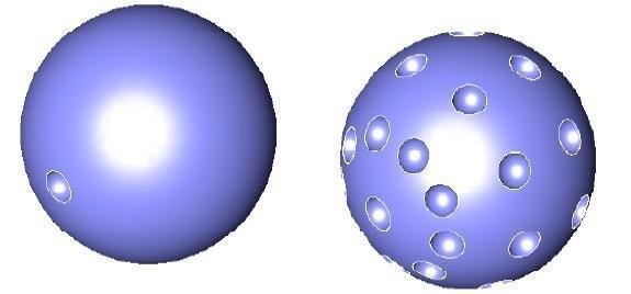
(a) Original (b) Spherical
Spherical Feature
Along Path
Creates a pattern along a curve path.
(a) Original (b) Along Path
Along Path Feature
Copy to Locations
Creates a pattern by specifying locations.
(a) Original (b) To Locations
To Locations Feature