Sheet Tools
Model to Sheet
This tool creates a 2D drawing from the selected objects. The Model to Sheet tool automatically creates a new layer called Sheet #. Nested layers for the title block, dimensions, and drawing data are also created.
Using the Model to Sheet Tool
- Select curves, surfaces or solids for placement into a drawing sheet.
- Set the appropriate options in the Model to Sheet dialog box.
New Drawing View
Creates a new and empty drawing view. To add geometry to a new drawing view, select the geometry and copy it with the Edit: Copy tool. Then activate the view such that its border is red. Finally, use the Paste tool to add geometry to the view. The geometry in the view is associative to the original copy. Geometry created in an activated view is displayed only in that view.
Creating New Draw Views
- Click the upper left corner position of the draw view.
- Click the lower right corner position of the draw view.
New Draw View
To place objects (curves, surfaces, solids) into a draw view follow the directions below:
Adding Objects to a Draw View
- Use the Arrow tool to select the objects to add.
- Select the Edit: Copy command to copy into the paste buffer.
- Click on the draw view to activate.
- Select the Edit: Paste command to put the objects into the draw view.
The objects placed in the draw view are associative to the original parent objects.
Auxiliary View
Creates an Auxiliary View from a referenced drawing view. Define the fold line with two points referenced from the parent view. Move the view and it will align automatically.
Creating an Auxiliary View
- Click in the draw view to create an Auxiliary View from.
- Click two points representing the fold line.
- Move your cursor to locate the new Auxiliary View.
The direction of the fold line defines the line of sight. Changing the order of the two points will flip the direction. You can also edit the flip direction of the auxiliary view dimension in the info dialog box.
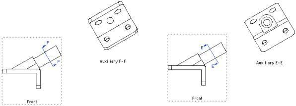
Auxiliary Views
Section Views
The Section View tools allow you to create horizontal, vertical, and a variety of other views through parts. The section dimension is associative to the section view. Moving the dimension will automatically update the section view. Section views are associative to the geometry that they are created from and the location of the section dimension. By moving the section dimension in the parent view, the section will automatically update.
Vertical Section View
This creates a view, vertically, through a part.
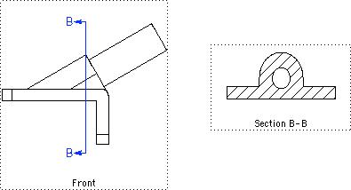
Using the Vertical Section View tool
- Click the Vertical Section View tool.
- Click a start point to define the section position.
- Drag your cursor to position the view.
Horizontal Section View
This creates a view, horizontally, through a part.
Using the Horizontal Section View tool
- Click the Horizontal Section View tool.
- Click a start point to define the section position.
- Drag your cursor to position the view.
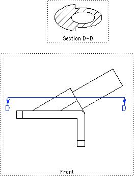
Arbitrary Section View
This allows you to define a view through a part.
Using the Arbitrary Section View tool
- Click the Arbitrary Section View tool.
- Click a start point to define the section position.
- Drag your cursor to position the view.
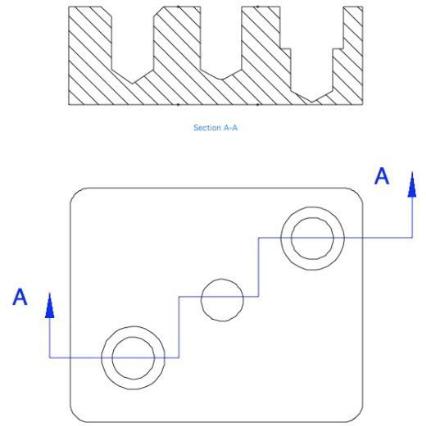
Offset
The Offset Section tool creates a sectional drawing view through a cutting plane, bent at right angles, to features as though they were in the same plane. A frequent use for an offset section is to provide a section view through a variety of hole centers.
Using the Offset Section View tool.
- Select the Offset Section tool.
- If a draw view is not active, click in the draw view that will contain the section annotation.
- Enter locations for Offset corners. Right--click when completed.
- Move the offset draw window to the desired location.
Break-away
The Break-away Section tool lets you define regions of a part you want to break away to display interior features of a part.
Using the Break--away Section View tool
- Select the Break--away Section tool.
- Select the closed curves to define the break away region.
- Pick a draw view from which to define the depth to the break.
- Pick a point to define the depth.
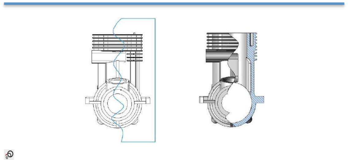
Drag the new section view to a location on the drawing.
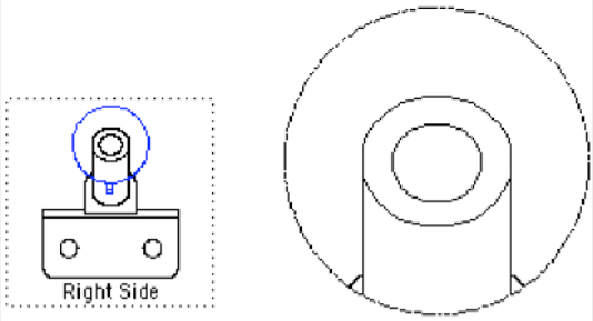
Detail View
Creates a detail view from a draw view. The detail dimension is associative to the detail view. Moving the detail dimension will automatically update the detail view. Detail dimensions are associative to the geometry in the parent view as well as the location and diameter of the detail dimension. Moving the circular dimension will automatically update the detail dimension.
Creating a Detail View
- Click a point defining the detail center.
- Click a point defining the detail radius.
- Move your cursor to locate the new detail view.
- Use the Data Entry Fields to change the detail scale.
Regen View
The Regen View tool is used to update all Draw Views that are out of date or in need of regeneration. A draw view becomes out of date if the geometry within the draw view changes. Normally draw views are updated automatically. However, there is an option in the Draw View Properties dialog box for manually controlling regeneration of draw views. If you turn on Regen Manually, draw views will ONLY regenerate if you select the Regen View tool icon.