Wood Working Joints
(Available in ViaCAD Pro Only)
The Woodworking tools are available to create joints for intersecting and adjoining objects. You can create joints at edges or on surfaces using the available tools.
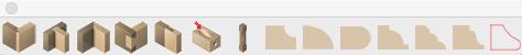
Rabbet Joint
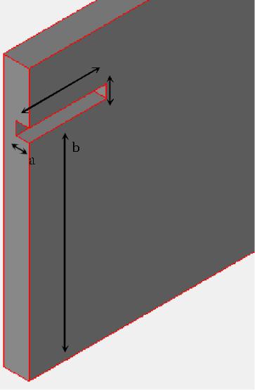
A rabbet joint creates a cutaway joint for two intersecting edges. This type of joint is only needed on one of the two edges. This joint is defined by a depth and width, which should correlate to the depth and width of the adjoining edge. To edit a joint after it has been placed, select a face on the joint and its properties appear in the Prompt Window.
-
Depth- defines how far into the face the joint extends; this should reflect the length of the adjoin edge.
-
Width- defines the size of the joint, or gap; this should reflect the width of the adjoining edge.
Using the Rabbet Joint tool
-
Click the Rabbet tool from the Woodworking toolbar.
-
(optional) Edit the Depth and Width values (be sure to press Enter to accept new values).
-
Select the edge where the objects connect. The joint runs parallel to the edge you select.
-
Select the face for the joint where the edges connect.
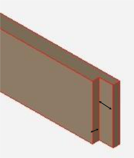
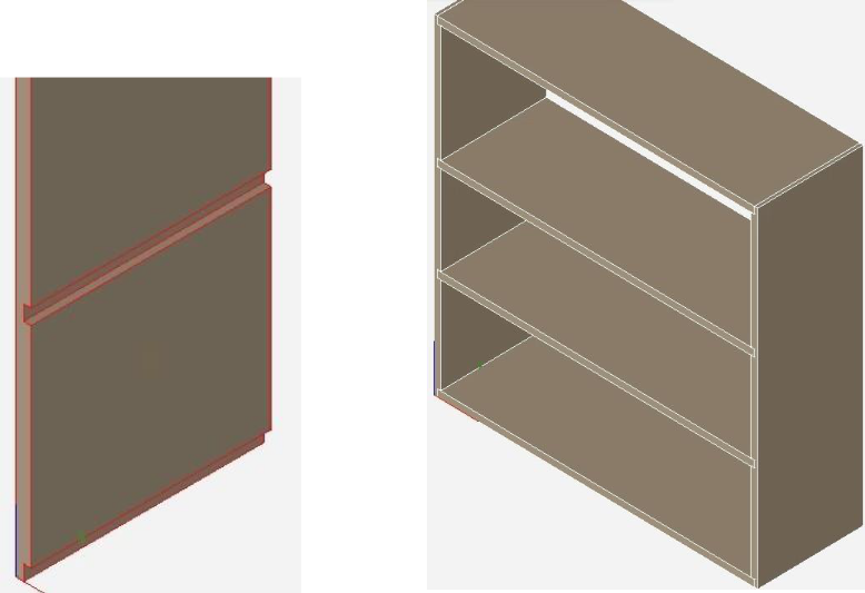
Rabbet joint addedRabbet joint with adjoining edge
Dado Joint
A dado joint creates a cutaway joint on a surface where an adjoining edge can fit. There are four dado joint methods:
- Through- Extends across an entire surface
- Stopped- Extends a user-defined distance across asurface.
- Blind- Offset from edges within a surface.
- Custom- A non-linear or angular joint based on a user-defined curve or line.
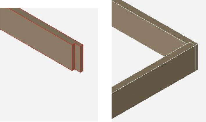
Through Joint
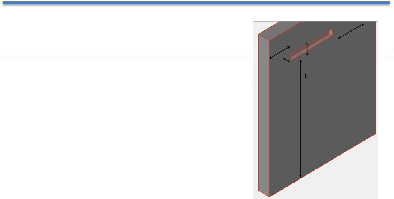
The Dado Through method extends a joint across an entire surface, running parallel to an existing edge. A practical example would be a joint on the side of a bookcase to create an opening where you can slide in a shelf. The edge and distance from that edge are both user-defined. The size of the joint is defined by a depth and a width value, which should correlate to the depth and width of the adjoining edge. These values can be defined before or after the joint is placed.
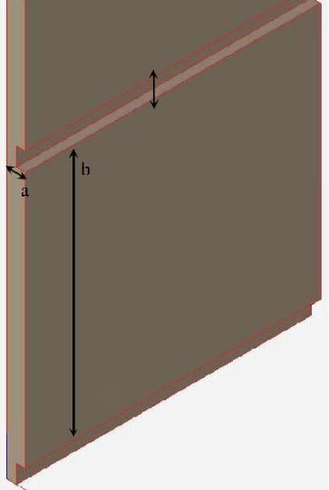
Depth- defines how far into the face the joint extends; this should reflect the length of the adjoin edge.
From Edge-
defines the distance from the user-defined edge thth the joint is positioned
Width- defines the size of the joint, or gap; this should reflect the width of the adjoining edge.
Creating a dado through joint
-
Click the Dado tool from the Woodworking toolbar.
-
On the Prompt Window, choose Through from the Method drop--down.
-
(optional) Edit the From Edge, Depth, and Width values (be sure to press Enter to accept new values).
-
Select the edge along which the joint should run parallel. The distance from this edge is determined by the From Edge value.
-
Select the face for the joint. The joint appears based on the values you’ve specified. You can edit these values to adjust the joint at any time.
The Dado Stopped method extends a joint into a surface based on a user-defined distance, running parallel to an existing edge. This type of joint stops when the distance has been reached. The edge and distance from that edge are both user-defined. The size of the joint is defined by a depth and a width value, which should correlate to the depth and width of the adjoining edge. These values can be defined before or after the joint is placed.
| a. Depth- defines how far into the face the joint extends; this should reflect the length of the adjoining edge.b. From Edge- defines the distance from the user-defined | |
|---|---|
| c. Width- defines the size of the joint, or gap; this | |
| should reflect the width of the adjoining edge. | |
| d. Stop Length- defines the length of the joint. After this | |
| distance is reached, the joint stops. |
Creating a dado stopped joint
- Click the Dado tool from the WoodWorking toolbar.
- On the Prompt Window, choose Stopped from the Method drop-•down.
- (optional) Edit the From Edge, Depth, Width, and Stop Length values (be sure to press Enter to accept new values).
-
Position your cursor on the edge along which the joint should run parallel, on the side of the edge you want the joint placed, and select the edge. The distance from this edge is determined by the From Edge value.
-
Select the face for the joint. The joint appears based on the values you’ve specified.
You can edit these values to adjust the joint at any time.
Blind Joint
The Dado Blind method positions an offset joint within a surface based on user-defined start and end distances, running parallel to an existing edge. The edge and distance from that edge are both user-defined. The size of the joint is defined by a depth and a width value, which should correlate to the depth and width of the adjoining edge. These values can be defined before or after the joint is placed.
-
Depth- defines how far into the face the joint extends; this should reflect the length of the adjoining edge.
-
From Edge- defines the distance from the user-defined edge the joint should be positioned.
-
Width- defines the size of the joint, or gap; this should reflect the width of the adjoining edge.
-
Blind End- defines the distance from the end of the joint to the edge of the face.
-
Blind Start- defines the distance from the start of the joint to the edge of the face.
Creating a dado blind joint
- Click the Dado tool from the WoodWorking toolbar.
- On the Prompt Window, choose Blind from the Method drop-•down.
- (optional) Edit the From Edge, Depth, Width, Blind Start, and Blind End values (be sure to press Enter to accept new values).
- Select the edge along which the joint should run parallel and select the edge. The distance from this edge is determined by the From Edge value.
- Select the face for the joint. The joint appears based on the values you’ve specified.
You can edit these values to adjust the joint at any time.
Custom Joint
The Dado Custom method allows you to specify a curve or line to create non-linear or angular dado joints. This type of joint is defined by a depth, width, and user-defined curve that exists on the surface. Before using the joint tool, the curve you want to use should exist on the surface where the joint will appear. If the joint is to extend through an edge, be sure the curve extends beyond the that edge to ensure the joint extends all the way through. The resulting dado joint is associated with the curve or line, so if changes are made to the curve they are applied to the joint.
Creating a dado custom joint
- Click the Dado tool from the Woodworking toolbar.
- On the Prompt Window, choose Custom from the Method drop--down.
- (optional) Edit the Depth and Width values (be sure to press Enter to accept new values).
- Select the curve or line to be used as the dado joint model.
- Select the face for the joint. The joint appears based on the values you’ve specified. You can edit these values to adjust the joint at any time.
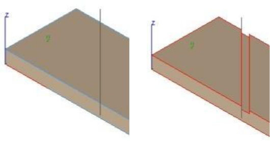
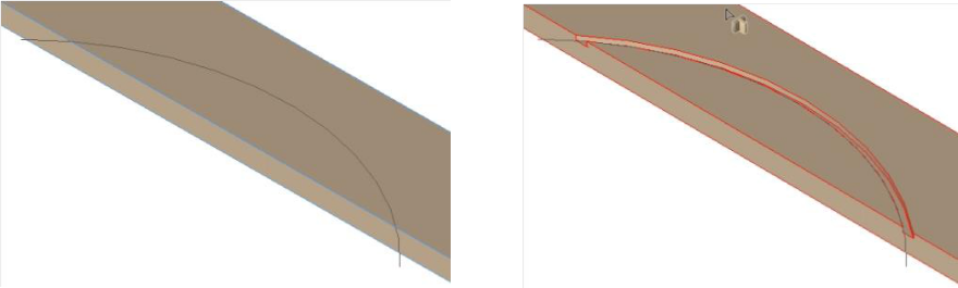
Custom Dado from Angled Line Custom Dado from Curve
Miter
A miter joint creates a 45-degree angle at the selected edge.
Creating a mitered joint
- Click the Miter tool from the Woodworking toolbar.
- Select the edge you want to miter. The edge forms a 45--degree angle.
DoveTail
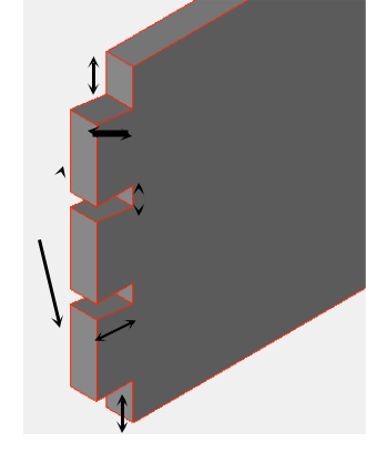
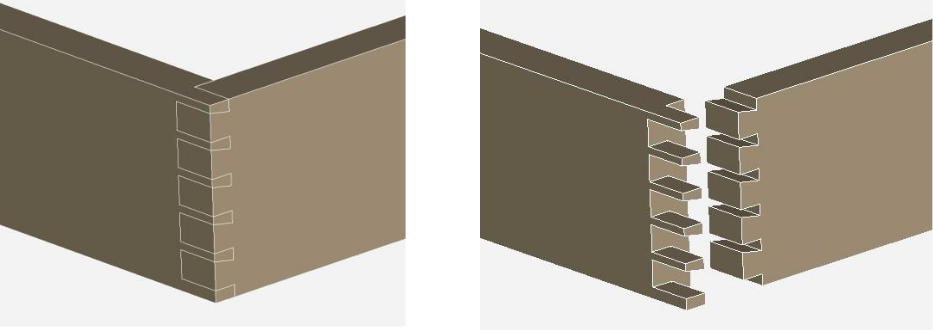
A dovetail joint is made up of a series of tails and pins between adjoining edges. The joint is created by specifying the tail board properties; the associated pin board edge is dependent on those settings.
- Tails- defines the number of tails.
- End Pin- defines the distance between the end pins and the end of the face.
- Tail Depth- defines how deep into the object the tails extend.
- Pin Width- defines the distance between each tail and the width of the corresponding pin.
- Angle- defines the angle of the top of the tails (cannot be a negative value).
Creating a dovetail joint
- Click the Dovetail tool from the Woodworking toolbar.
- On the Prompt Window, choose Tail Board from the Method drop--down menu.
- (optional) Edit the Tails, End Pin, Tail Depth, Pin Width, and Angle values (be sure to press Enter to accept new values).
- Select the object face for the tails. The tails are added. Continue to select edges if additional tails are needed.
- On the Prompt Window, choose Pin Board from the Method drop--down menu.
- Select the object face for the pins and then select the object with the associated tails. The joint is created.
Tongue & Groove
A tongue & groove joint creates an inset groove and a protruding tongue that are used to connect two adjoining edges. This type of joint is defined by a depth and width and is positioned parallel to two user-defined edges. The depth and width values apply to both the tongue and groove.
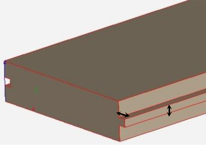
- Depth- defines how far in the groove is set, and how far out the tongue extends.
- Width- defines the overall size of the groove and tongue.
Creating a tongue & groove joint
- Click the Tongue & Groove tool from the Woodworking toolbar.
- (optional) Edit the Depth and Width values (be sure to press Enter to accept new values).
- Select the edge along which the tongue runs parallel.
- Select the edge along which the groove runs parallel.
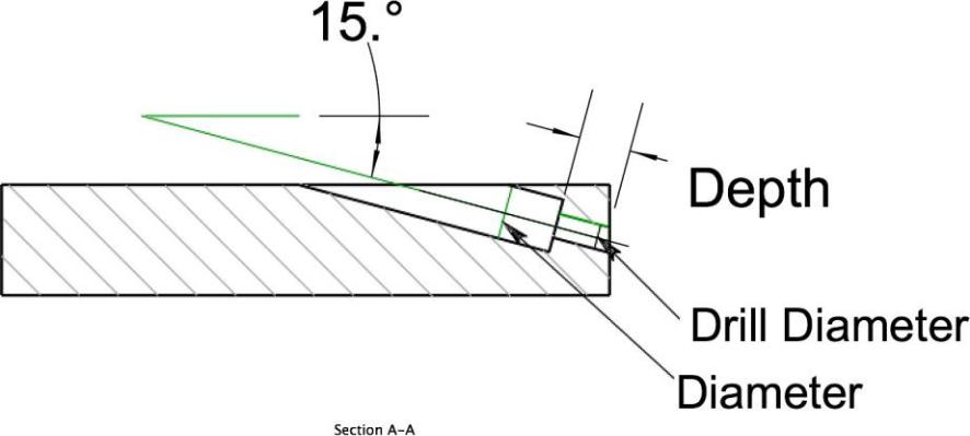
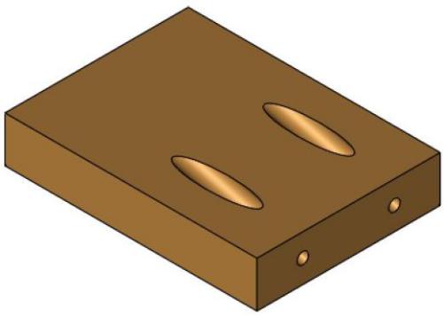
Pocket Hole Joint
A Pocket Hole joint is an angled counter bore through a part. up of a series of tails and pins between adjoining edges. The joint is created by specifying the tail board properties; the associated pin board edge is dependent on those settings.
- From Edge- distance pocket hole center from boardedge.
- Tip Diameter- diameter of hole exiting middle of board pins and the end of the face.
- Drill Diameter- diameter of hole entering wood.
- Depth – Length of tip diameter hole from exit.
Creating a Pocket Hole joint
- Click the Pocket Hole tool from the Woodworking toolbar.
- Specify distance from board edge.
- Specify bore and tip diameters
- Specify depth of tip.
- Select the board edge. (Edge distance is along this selection)
- Select the board face. (Counter bore hole starts at this face)
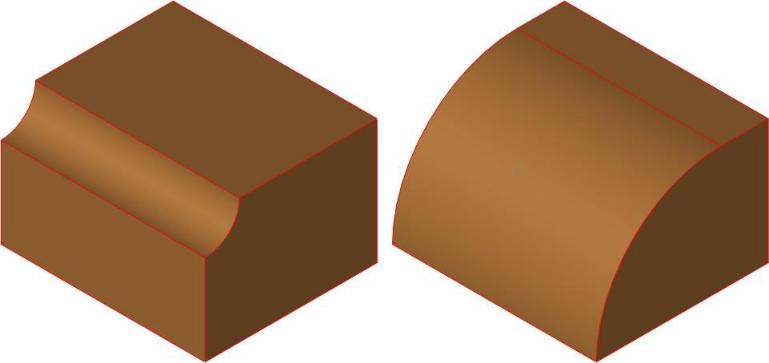
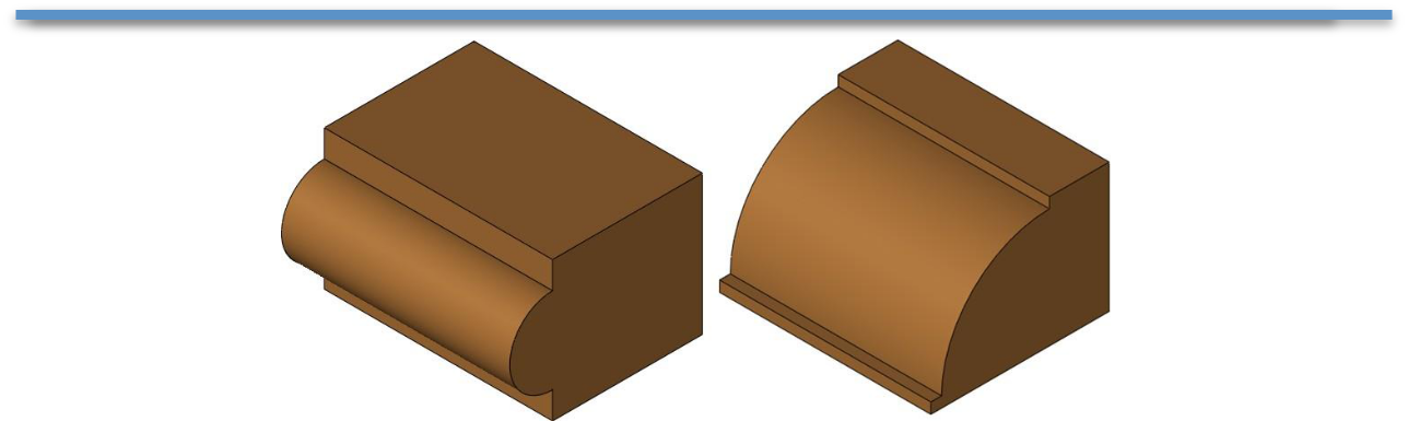
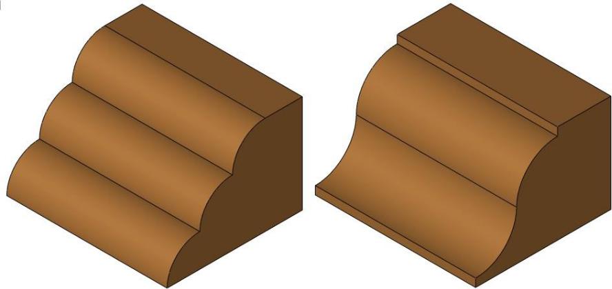
Edge Features
Edge features introduced in v12 provide a means to rapidly define parametric edges used in wood, marble, or granite designs.
Some predefined edge treatments include:
Cove Edge User can define the radius
Round Edge No requirements. Process is automatic
Bullnose Edge User can define the Bead height
Dupont Edge User can define the Bead & offset
Waterfall Edge No requirements. Process is automatic
Ogee Edge User can define the Bead height
Custom Profile User can select curves in XY plane
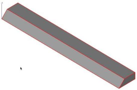
Stopped Chamfer
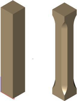
A Stopped Chamfer replaces an edge with a bevel, typically for decorative purpose. The bevel starts and ends by a user specified value. Parameters used to define a Stopped Chamfer are;
—Chamfer Length
—Distance from Start
—Distances from End
The transition rolls off using a smooth arc simulating the path of a router bit. As with other features, the user can modify any of these parameters during the design process to explore alternative shapes quickly.