Viewing in 2D&3D
FloorPlan Home Design Software provides many options for looking at your design onscreen. You can display several windows, each containing a different view of your plan. This gives you the flexibility to view your drawing as a 2D plan, as a 2D plan with a corresponding 3D view, or using only FloorPlan 3D View.
When viewing your 2D home plan, you can magnify the view by zooming in, reduce the view by zooming out or pan the view in any direction.
3D viewing provides many options, from walking through the home plan to flying around the plan or viewing the framing or completion phase of your project. You can adjust 3D display settings using a variety of viewing features, including adding shadows, for a realistic effect, or adjusting the lighting intensity of the view. Finally, you can create a photo-realistic view of your design.
Viewing the 2D Plan
When initially designing your plan, you will probably want to view the 2D plan view only. Once completed, you can view your plan in a combination of 2D and 3D or in 3D only. In addition, FloorPlan organizes your floor plan into layers, which are each easily accessible with a single mouse click. For example, you can choose to view the deck plan with landscaping one moment, then quickly switch to view electrical and plumbing. Any combination ... any time!
To view the 2D plan only
■ In the Plan toolbar, click the 2D Plan View button  . The 2D plan view appears.
(alternatively) Choose Design > Design Mode > 2D Plan View (or press Option-Command-1).
To view all 2D floor plan views at once
■ Click the Floors pop-up menu  in the toolbar and choose View All Floors.
(alternatively) Choose 2D > Floor Visibility > View All Floors.
(alternatively) Press two fingers on the trackpad and choose View All Floors from the shortcut menu.
To view the working floor only
■ Click the Floors pop-up menu  in the toolbar and choose View Working Floor Only.
(alternatively) Choose 2D > Floor Visibility > View Working Floor Only.
(alternatively) Press two fingers on the trackpad and choose View Working Floor Only from the shortcut menu.
Customizing Visible Plans
During the design of your floor plan, there may be times when you want certain layers that by default are hidden, to be visible. For example, while working on your electrical plan, you may need to see where the plumbing will be. FloorPlan makes it easy to customize how you view your plan layers.
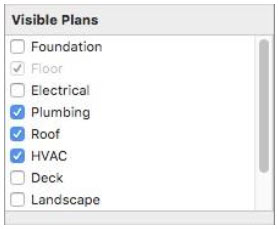
Note: Items on a hidden plan layer are not available during a Select All process and will not be altered with the other items and features in your drawing.
You can also assign custom colors to areas of your design, such as plans, inactive floors, gridline colors, and the color of your crosshair. These color settings, and more, can be customized by accessing the Preference window. For more information, see “Design Colors”.
To view a plan layer
1 In the toolbar, click the Plan tab you want to customize. The changes you make only affect the active plan.
2 Make sure nothing is selected in the 2D or 3D views and then click the Properties tab  in the right sidebar. The Plan and Editing settings appear.
3 Select the plan(s) you want to be visible in the design window or deselect the plan(s) you want to hide.
Control Topography Lines Visibility
There may be times when you will want to work on the Landscape Plan, but you may want to hide the topography lines. Topography lines are displayed when the Landscape plan tab is enabled, but you have the option to display or hide the topography lines.
To control topography lines visibility
■ Chose 2D > Show Topography Lines or Hide Topography Lines to hide them.
Zooming In and Out in 2D
You can get a closer look at an area or see a larger portion of your plan drawing by zooming in and out. By dragging over the drawing, the view enlarges or decreases dynamically. You can also set the zoom factor to obtain exact zoom precision. Once you’ve finished viewing your plan close-up, you can return to the previous full view with one mouse click.
To zoom
1 Choose the Zoom button  from the Editing Tools group.
2 In the design window, drag up to zoom in (or drag down to zoom out).
Note: The location of the pointer is centered in the design window.
To zoom using the trackpad
■ Position the cursor at the center of what you want to view and then pinch to zoom in or out.
To set the zoom factor
1 Choose 2D > Set Plan View Zoom. A dialog appears.
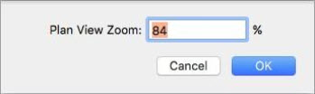
2 Enter a new zoom factor, then click OK.
To reset the 2D plan view
■ Choose 2D > Reset Plan View (or press Command-R). The plan is reset to the original, default view.
Panning Across the 2D Drawing
You can move the design window to see portions of the plan which are outside the current view, by panning. Panning also makes it easy to slowly view areas of your drawing piece-by-piece.
To pan in any direction
1 Choose the Pan button  from the Editing Tools group. The pointer changes to reflect pan mode.
2 In the design window, drag in the direction you want to move. The view changes dynamically as you drag.
To pan using the trackpad
■ Use two fingers on the trackpad to position your drawing.
Fitting Your Design to Your Current Window Size
You can quickly position your entire design within your window, without using the Pan button or Zoom button.
To fit your entire design within your window
■ Choose 2D > Fit to Window.
Configuring the Toolbar Display
The toolbar at the top of the application has four views:
■ Hidden The toolbar is not visible, maximizing the space on the design window.
■ Icon Only Shows just the toolbar icons
■ Text Only Shows just the descriptive text in the toolbar
■ Icon and Text Shows the toolbar icons and descriptive text
To configure the toolbar display
■ Right-click the toolbar and choose the type of display you want.
Note: You can also hide/show the toolbar from the View menu.
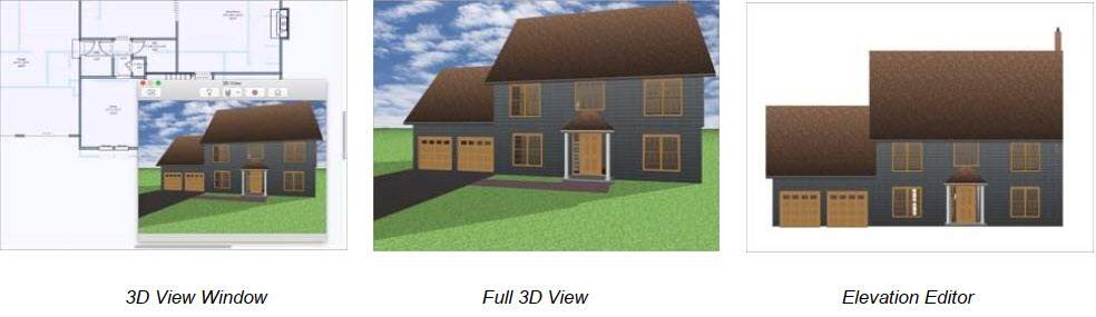
Working with 3D Views
FloorPlan Home Design Software lets you view your design in photo-realistic 3D. You can select exterior and interior wall color, add realistic roof materials and select from a variety of wood textures to make your design completely unique. Using a 3D view, you can see your design from a variety of angles and access a number of render styles, including the powerful ClearView, where you can literally see through the walls and view electrical, plumbing, and so on. The 3D views are available on the toolbar.
To reset the 3D view
■ Choose 3D > Reset 3D View (or press Shift-Command-R).
To display a floating 3D view 
■ Choose 3D Window View from the 3D View pop-up menu. A floating 3D view appears.
You can drag to move the window, or resize by dragging an edge or corner.
(alternatively) Choose Design > Design Mode > 3D Window View (or press Option-Command-3).
To display a 3D view only 
■ Choose 3D Full View from the 3D View pop-up menu. A full 3D view appears.
(alternatively) Choose Design > Design Mode > 3D Full View (or press Option-Command-2).
Note: You can hide the left and right sidebars to create a larger 3D view.
To display Elevation Editor view 
Choose Elevation Editor from the 3D View pop-up menu.
(alternatively) Choose Design-> Design Mode > Elevation Editor (or press Option-Command-4)
There are predefined views available in the toolbar. Choose one of the views to quickly see your design from that direction, or click the Rotate Elevation View Angle button and drag in the view window to rotate around the design.

You can add doors, windows, and accessories while in Elevation View by selecting one of the tools and then clicking on a wall to place. For more info on editing door, window, and accessory properties see “Floor Plan Tab”. While in Elevation View, you can also edit roofs, decks, and 3D objects that exist in your design.
To display Real Model view
■ Choose RealModel  from the 3D View pop-up menu. The view changes to RealModel and the RealModel menu becomes available.
(alternatively) Choose Design > Design Mode > RealModel (or press Option-Command-5). For more information, see “Preparing to Construct a RealModel”.
Using 3D Cutaway
With FloorPlan’s 3D Cutaway tool, you peel away layers of your floor plan with ease. You can slice away layer after layer of your design from nearly any angle, making it easy to see room arrangements, furniture placement, and more. You can add as many cutaway lines as you’d like, but only one can be active at a time. The 3D Cutaway button is available from the Editing Tools group and is placed in the design window where you define the length and angle of the cutaway line. There are three directions you can cutaway, which are available on the Properties pane when the cutaway line is selected.
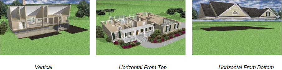
Cutaway Vertically
The vertical direction gives you a dollhouse view of your design, allowing you to see inside. When the vertical direction is active, arrows appear on the cutaway line showing you the direction you are cutting away. You can flip the direction easily on the Properties pane.
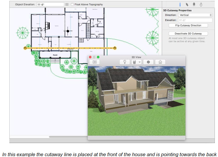
To place a vertical cutaway
1 Choose the 3D Cutaway  button from the Editing Tools group.
2 Use the Drag-to-Size drawing method to drag the cutaway line to the length and angle you want. Once placed, you can drag the line to a new position to adjust the cutaway.
3 On the Properties pane, choose Vertical from the Direction pop-up menu.
(optional) Click the Flip Cutaway Direction button to choose which direction is cutaway. The arrows on the endpoints of the cutaway line point towards the direction being cutaway.
4 Choose 3D Window View from th e 3D View pop-up menu and set your 3D view.
To control a cutaway display
1 Select the cutaway line you want to activate or deactivate.
2 On the Properties pane, click Deactivate 3D Cutaway to disable it or Activate 3D Cutaway to enable it.
(alternatively) Right-click the cutaway line and choose to Deactivate 3D Cutaway to disable it or Activate 3D Cutaway to enable it.
Cutaway Horizontally
You can cutaway horizontally from the top or the bottom of your design. When one of the horizontal cutaway directions is selected, you can set the elevation for the cutaway line to control how much of your design is cutaway. The elevation is an absolute measurement from 0 rather than relative to the top or bottom of your design. For example, if your cutaway elevation is 8'-0", your design is cut away from the top down to 8'-0", or from the bottom up to 8'-0". When placing a cutaway line to cut away the top or bottom of your design, the length and direction of the line are not important because the cutaway plane is based on the elevation of the line rather than the angle or length.
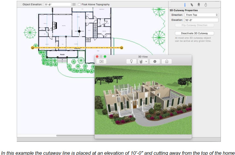
To place a horizontal cutaway
1 Choose the 3D Cutaway  button from the Editing Tools group.
2 Use the Drag-to-Size drawing method to drag the cutaway line to the length and angle you want. Once
placed, you can drag the line to a new position to adjust the cutaway.
3 On the Properties pane, choose From Top or From Bottom from the Direction pop-up menu.
(optional) Enter the Elevation you want for the cutaway line and press the Return key.
4 Choose 3D Window View  from the 3D View pop-up menu and set your 3D view.
To control a cutaway display
1 Select the cutaway line you want to activate or deactivate.
2 On the Properties pane, click Deactivate 3D Cutaway to disable it or Activate 3D Cutaway to enable it.
(alternatively) Right-click the cutaway line and choose to Deactivate 3D Cutaway to disable it or Activate 3D Cutaway to enable it.
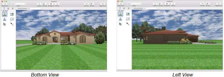
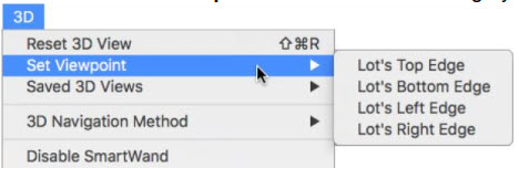
Setting the Viewpoint Angle
FloorPlan has four preset viewpoint angles and, from those angles, moving to the needed viewpoint is easy. Below is an example of the Right View. By clicking the other three directions, you can view your floor plan from the other edges of your lot.
To set a viewpoint angle
1 Choose 3D Full View  from the 3D View pop-up menu. A full 3D view appears.
2 Choose 3D > Set Viewpoint and choose the lot edge you want to view from.
Selecting Features in 3D
With FloorPlan’s 3D Select Objects button, you can click features in a 3D view window and they are automatically selected on your 2D plan. This makes fine-tuning your design much easier. For example, you can easily select windows that may be stacked on top of each other in the 2D plan by clicking the window you want to select in 3D. In the image below we’ve selected a table setting in the 3D view, and it is selected in the 2D plan and its properties appear on the Properties pane.
**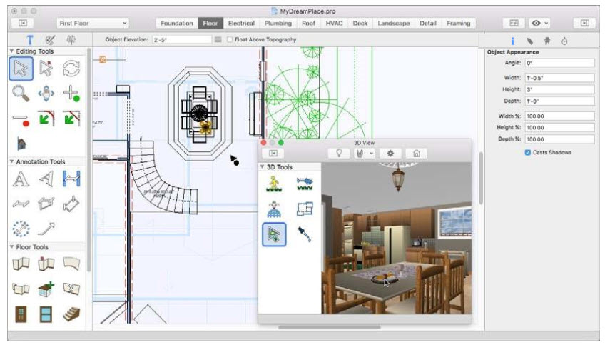
Note: You can select features on the active floor and active plan only. If the feature you click does not become active, make sure it is on the active floor and plan.
To select objects in the 3D view
1 Choose the Select Objects  button from the 3D Tools group.
2 In the 3D View window, click to select a feature. That feature is activated in the design window and its properties appear on the Properties pane.