Roofing Plan Tab
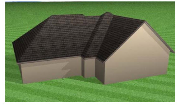
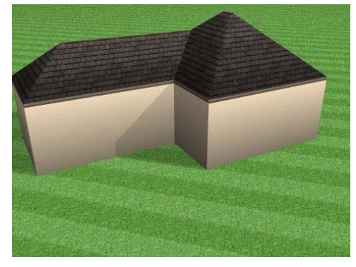
One of the features that will set your design apart from all others will be its roofline. Using the roofing tools available in FloorPlan Home Design Software, you can design intricate roofs with ease. From basic rooflines, like hipped or gable, to less common ones, like saltbox, gambrel, or a roof over a bay window. You will be able to create any roof to match the style of your home plan.
The Roof Tools are available in the left sidebar. For information on accessing the left sidebar, and controlling the display of the tools that appear, see “Left Sidebar”
Generating a Roof Automatically
You can add a hip roof to an enclosure with just two mouse clicks. The roof panels are created, matching the wall pitch. The roof’s properties are controlled by the Roof Options, where you can specify the roof pitch, soffit depth, generation preferences, and framing options. After an auto-roof is generated, edit the roof panels as you would a typical, manually drawn roof, and the panels can be updated when you make changes to the perimeter walls. To remove the roof, delete the roof panels in the design window. To control auto-roof settings, see “Auto-Roof Properties”
To auto-generate a roof
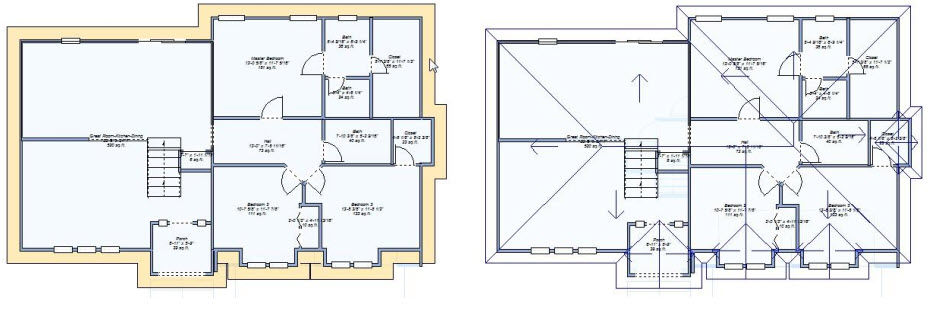
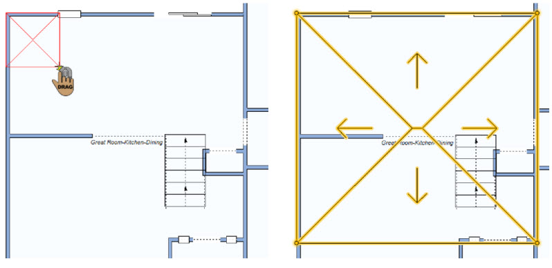
1 In the design window, click near the perimeter of the exterior walls. The entire perimeter appears highlighted.
2 Click the Properties  tab in the right sidebar and, under Auto-Roof Properties, click the Generate Roof button. A hip roof is generated based on the current automatic roof options.
Auto-Roof Properties
Automatic roofs are built instantaneously, however can control the settings that are used and update the roof if you need to adjust it. Auto-roof properties are controlled in the Automatic Roof Options window.
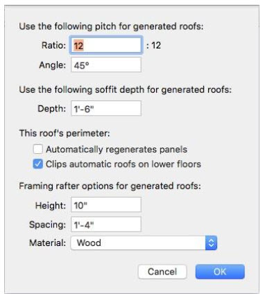
Roof Pitch Enter the Ratio or Angle to specify how you want to set the roof pitch and then type the pitch you want in the corresponding text field.
Soffit Depth Enter the depth you want in the Depth field.
Roof Perimeter
When the “Automatically regenerates panels” checkbox is selected, the roof panels are created automatically, and updated automatically if the perimeter walls are moved or resized. When deselected, you must click the Generate Roof button on the Properties pane to generate the panels manually. When “Clips automatic roofs on lower floors” are selected, roof panels are removed from the interior of other levels so a roof is not built inside. When the “Generates eaves” checkbox is selected, eaves are automatically generated with the roof.
Framing Options control the underlying roof framing. To see the roof framing you must use the Framing render style in the 3D view. For more information, see “Accessing the 3D Rendering Styles”.
Rafter Height defines the height of the rather boards.
Rafter Spacing defines the distances between each rafter board.
Rafter Material pop-up menu specifies the rafter building material.
Note: For truss roof framing, you should create a roof using one of the roof shape tools or freehand roof tools.
To edit automatic roof properties
1 In the design window, click near the perimeter of the exterior walls. The entire perimeter appears highlighted.
2 Click the Properties  tab in the right sidebar and, under Auto-Roof Properties, click the Roof Options button.
3 Edit the options as needed and then click OK.
Drawing a Roof Shape
There are several styles of roofs available in FloorPlan Home Design Software. Automatic dimensioning makes it easy to achieve exact placement. When the tool is active you can edit the properties on the Properties pane. You can also edit the properties after the roof has been placed by selecting the roof in your drawing. Be sure you are working on the floor where you want to add the roof. For example, to draw a roof over a one-story structure you should be on the first floor.
To draw a roof shape
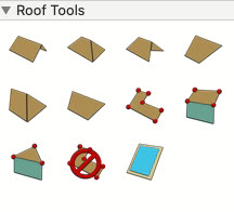
1 Choose the roof style you want from the Roof Tools group.
2 Use the Drag-to-Size drawing method to draw the roof to the shape and size you want.
Note The arrow shows which way the roof section descends. The elevation of each corner is noted.
Using the Freehand Roof Tools
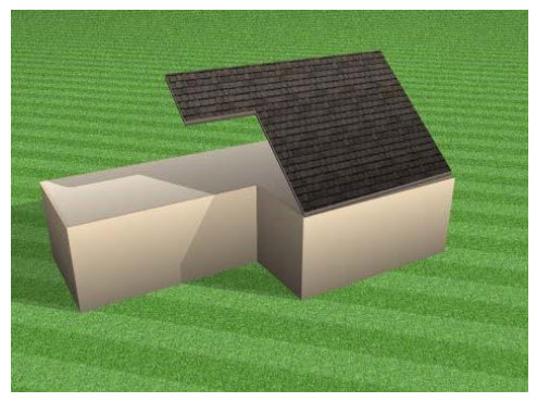
FloorPlan Home Design Software includes freehand roof tools that provide versatility and power when drawing complex roofing plans. Using the three-point and four-point freehand tools, roof sections are attached to walls, making it easy to draw them the necessary size the first time. After drawing roof sections, all parts of it can be customized, for example, pitch, placement, or shape. With the three- and four-point freehand tools you can specify a width for the soffit. You can resize and reshape the roof by dragging endpoints. You can also drag the arrow in the center of the roof section to rotate it and change the direction of the roof slope.
The following freehand roofs are available:
■ Freehand Roof
■ Four-Point Freehand Roof
■ Three-Point Freehand Roof
Freehand Roof
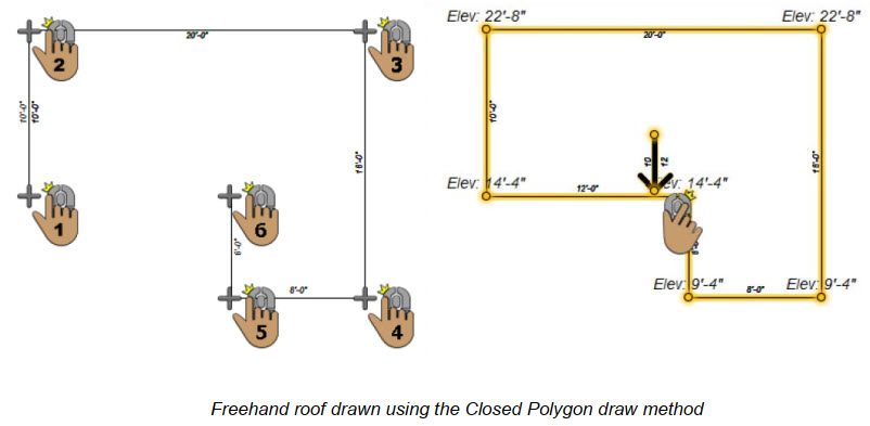
The Freehand Roof Tool allows you to create a roof section using a 2D shape draw method. You can set the pitch and the point to which the elevation is measured on the Properties pane before or after you add the roof. The elevation of each selected point of the roof section is notated; use these specs to match other roof sections.
To draw a freehand roof
1 Choose the Freehand Roof button from the Roof Tools group.
2 On the Properties pane, choose how you want to draw the shape.
3 Use the Define 2D Shape drawing method to draw a freehand roof section.
Four-Point Freehand Roof
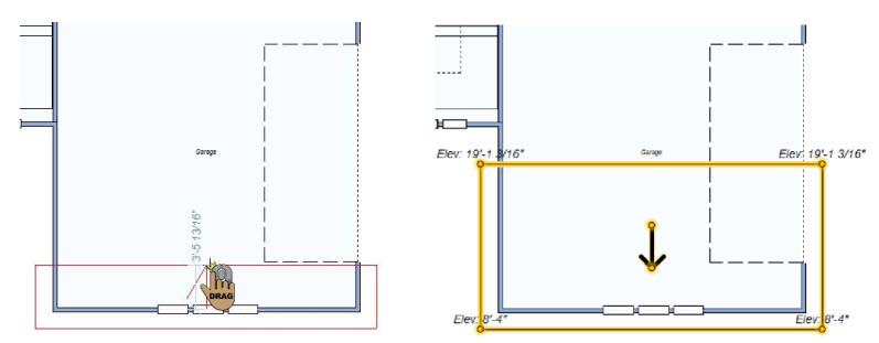
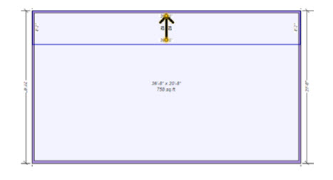
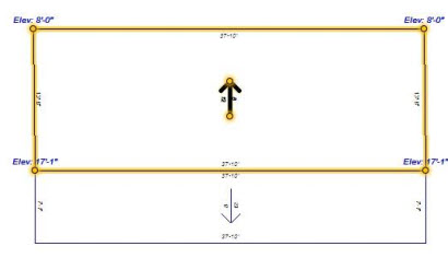
The Four-Point Freehand Roof Tool creates a rectangular roof section attached to a wall. The roof is drawn to cover the entire wall segment. You can define the pitch and the soffit settings on the Properties pane before you add the roof, and then edit the pitch and elevation after the roof has been placed. As you draw the roof, a rubber band line is displayed and follows the pointer. This line signifies the direction the roof section will rise. Also, dimensions are displayed as you draw.
To draw a four-point freehand roof
1 Choose the 4-Point Freehand Roof  button from the Roof Tools group.
2 Position your cursor on a wall in the design window then drag away from the wall section. Release the mouse button to place.
Note: The elevation of each selected point of the roof section is notated; use these specs to match other roof sections.
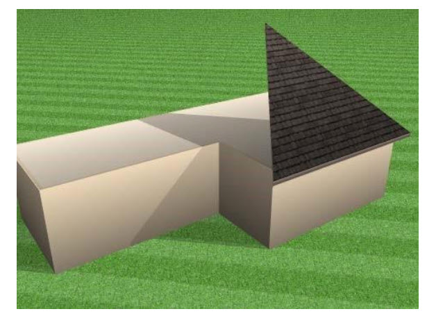
Three-Point Freehand Roof
The Three-Point Freehand Roof Tool creates a triangular roof section attached to a wall. The base of the roof is drawn to cover the entire wall segment. You can define the pitch and the soffit settings on the Properties pane before you add the roof, and then, if necessary, edit the pitch and elevation after the roof has been placed. As you draw the roof, a rubber band line is displayed and follows the pointer. This line signifies the direction the roof section will rise. Also, dimensions are displayed as you draw.
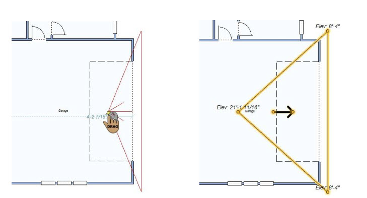
To draw a three-point freehand roof
1 Choose the 3-Point Freehand Roof  button from the Roof Tools group.
2 Position your cursor on a wall in the design window then drag away from the wall section. Release the mouse button to place.
Note: The elevation of each selected point of the roof section is notated; use these specs to match other roof sections.
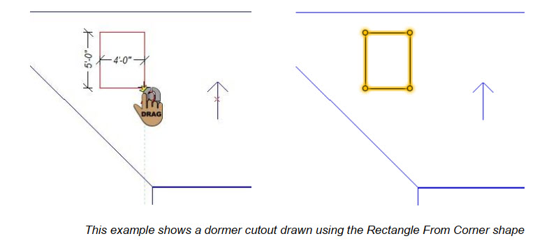
Creating a Dormer Cutout
A cutout tool is available for removing part of a roof panel. This way you can manually draw cutouts using the available draw method shapes. Dormer cutouts must be drawn on an existing roof panel in your design, and the entire shape must exist on the same roof panel.
To cut out a roof for a dormer
1 Choose the Dormer Cutout  button from the Roof Tools group.
2 On the Properties pane, choose how you want to draw the shape.
3 Use the Define 2D Shape drawing method to draw a freehand roof section.
Roof Properties
Once drawn, roof sections can be altered to suit your design. From resizing to rotating the slope to changing its pitch, FloorPlan Home Design Software makes it simple to create even the most complex roofline. Roofs are defined by their pitch, elevation, size, and their slope direction. You can edit the properties before you draw or after the component has been added to your design by selecting it and clicking the Properties tab in the right sidebar. Note: Press Return to accept new values in fields.
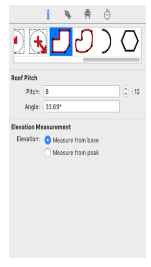
Pitch affects how steep a roof appears. For example, 10:12 means the roof rises 10" for every 12" of the roof. To create a flat roof, type 0.0 in the text field.
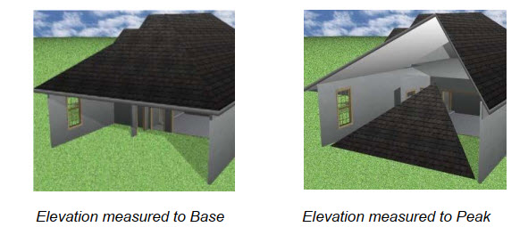
Elevation specifies whether the roof elevation is measured from the ground to the base of the roof section or from the ground to the peak of the roof section.
The angle allows you to specify an angle for the pitch. Enter a pitch of 0.0 in the field to create a flat roof.
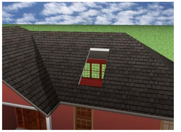
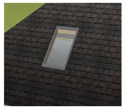
Adding a Skylight
Skylights are windows cut into the roof. They add a touch of elegance, in addition to letting in more natural light. When the tool is active you can choose the Skylight style you want on the Properties pane. You can also change the skylight style before or after it has been placed in your drawing. Skylights must be placed on an existing roof panel in your design.
To add a skylight
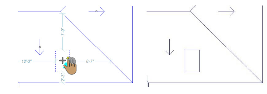
1 Choose the Skylight  button from the Roof Tools group.
2 Use the Click Once to Place drawing method to place the skylight in your design.
Skylight Properties
Skylights are defined by their width, height, and trim size. You can edit the properties before you draw or after the component has been added to your design by selecting it and clicking the Properties tab in the right sidebar. Skylight Style lets you choose the type of skylight you want to add to your roof. The Custom Skylight style includes a number of additional categories to choose
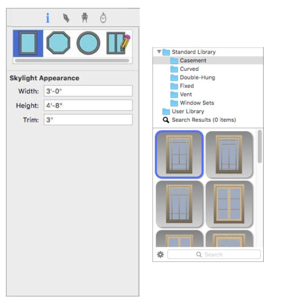
Width defines the distance from one side of the skylight to the other.
Height defines the distance from the bottom of the skylight to the top.
Trim defines the width of the trim around the skylight. This is not included in the overall height or width.
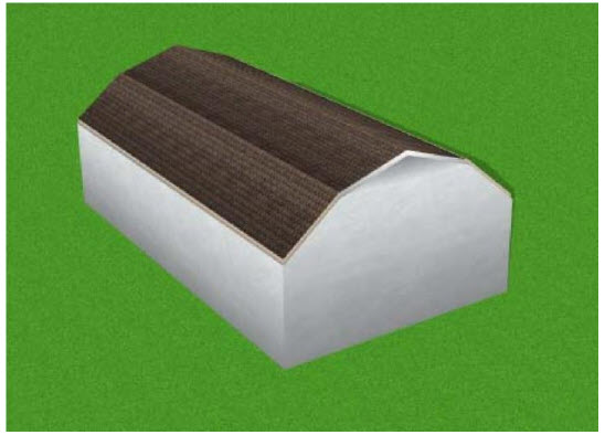
Drawing a Gambrel Roof
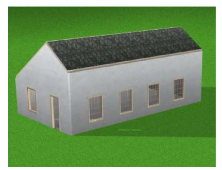
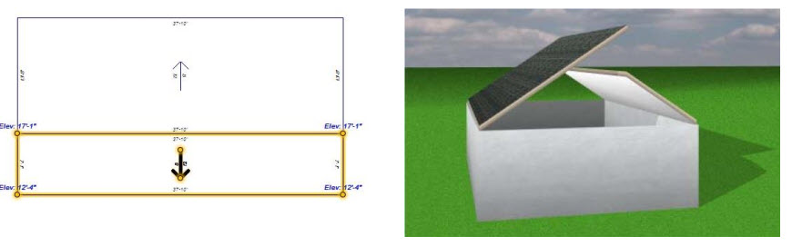
The Gambrel, or barn, the roof is a popular style because it increases the usable space in the loft/attic area. A gambrel roof is composed of two pitches. The lower sections are created using the Four-Point Freehand Roof Tool, while the upper pitch will be drawn using the Gable Roof Tool.
Note: The following example uses 12:12 and 4:12 pitches, but any combination of pitches will work for this roof. Use the four-point Freehand Roof button
To draw a gambrel roof
1 to draw a roof section on one of the walls.
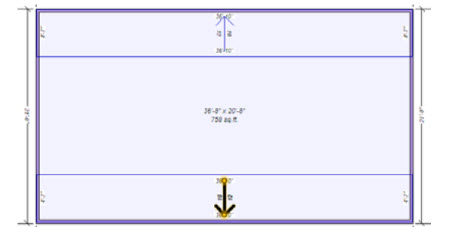
2 Draw a matching four-point freehand roof on the opposing wall using the same roof pitch.
.(alternatively) Use copy and paste to create a copy of the existing roof section and change the roof direction so the panel is the exact same dimensions. At this point there will be a gap between the two roof sections; this gap will be filled with the Gable Roof section.
Note: Note the elevation that is specified in red as the upper elevation of the roof section.
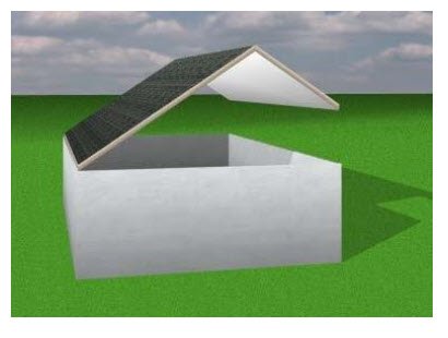
3 Use the Gable Roof Tool to draw a gable roof between the two freehand roof panels. The roof pitch should not be as steep as the lower roof sections.
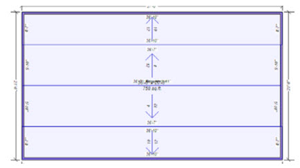
4 Elevate the gable roof to the top elevation of the freehand roof panels.
Note: The previous example specified 12:12 and 4:12 pitches, but any combination of pitches will work for this roof.
Drawing a Saltbox Roof
Saltbox roofs are similar to gable roofs, with an offset ridge. Although they are not symmetrical, they are extremely attractive and easy to create.
Note: The following example uses an 8:12 pitch and 1” soffit, but any combination of pitches will work for this roof.
To draw a saltbox roof
1 Use the Four-point Freehand Roof  button to draw a roof section on one of the walls. Make note of the peak elevation as you will set the next roof section to this elevation.
2 Draw a matching four-point freehand roof on the opposing wall using the same roof pitch.
3 Click to select the second roof section and, on the Properties pane, select Measure from peak to measure from the ground to the peak of the roof section.
4 While the roof section is selected, enter the peak elevation of the first roof section (created in step 1) and press the Return key to elevate the roof section.
5 Edit the wall properties to close the gable ends of this roof style. For more information, see “Wall Properties”