Detail Plan Tab
FloorPlan Home Design Software provides tools specifically for 2D drawing. Items drawn with these tools will not show up in the 3D View window unless they are converted to 3D entities. These tools make it easy to label your plan, from description blocks that are used to label what is being printed on each page to notations about square footage on each floor.
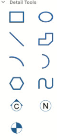
The Detail Plan features several tools for drawing basic shapes like rectangles, arcs, and curves. Methods for drawing these shapes are used throughout FloorPlan Home Design Software. The Detail Tools are available in the left sidebar. For information on accessing the left sidebar, and controlling the display of the tools that appear, see “Left Sidebar”.
Drawing Rectangles and Squares
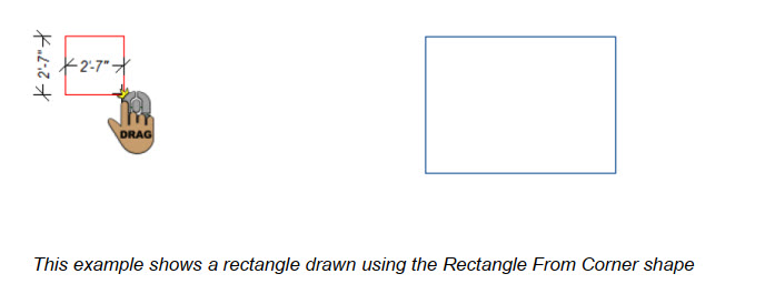
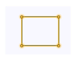
With FloorPlan Home Design Software, you can draw items that will appear only in the 2D design window. If you choose, these shapes can be converted to a variety of features, for instance, walls, stairways, pathways, edging, and more. Rectangles can also be used as label boxes for your printed plans or can be converted to walls or flooring. Before you draw, you can choose how you want to draw the shape on the Properties pane in the right sidebar.
To draw rectangles and squares
1 Choose the Rectangle  button from the Detail Tools group.
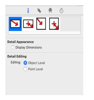
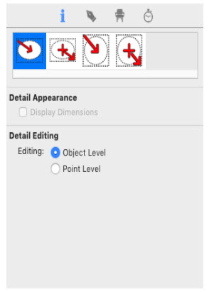
2 On the Properties pane, choose how you want to draw the shape.
3 Use the Drag-to-Size drawing method to set the angle and length for the shape.
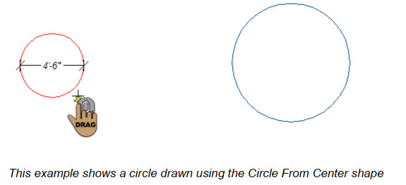
Drawing Circles and Ovals
You can draw circles and ovals, which can be converted to curved walls, curved stairways, ground fill regions, and other curved shapes. Before you draw, you can choose how you want to draw the shape on the Properties pane in the right sidebar.
To draw circles and ovals
1 Choose the Circle/Oval  button from the Detail Tools group.
2 On the Properties pane, choose how you want to draw the shape.
3 Use the Drag-to-Size drawing method to set the angle and length for the shape.
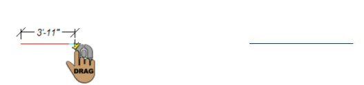
Drawing Lines
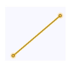
You can draw lines that can in turn be converted to walls, stairs, ducts, stiffener beams, edging, pathways, and more. Before you draw, you can choose how you want to draw the shape on the Properties pane in the right sidebar.
To draw lines
1 Choose the Line  button from the Detail Tools group.
2 On the Properties pane, choose how you want to draw the shape.
3 Use the Drag-to-Size drawing method to set the angle and length for the shape.
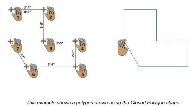
Drawing Polygons
You can draw open or closed polygons that can be easily converted into walls, roof sections, floors or floor cutouts, topography, and so on. Before you draw, you can choose how you want to draw the shape on the Properties pane in the right sidebar.
To draw a polygon
1 Choose the Polygon  button from the Detail Tools group.
2 On the Properties pane, choose how you want to draw the shape.
3 In the design window, click to set the start point and drag to define the length and angle of the polylines.
4 Continue to click points and drag to define the shape of the polygon and then right-click to place.
Drawing Arcs
With FloorPlan Home Design Software you can draw arcs that can be easily converted into curved walls, edging, stairs, and more. Before you draw, you can choose how you want to draw the shape on the Properties pane in the right sidebar.
To draw an arc
1 Choose the Arc  button from the Detail Tools group.
2 On the Properties pane, choose how you want to draw the shape.
3 Use the Drag-to-Size drawing method to set the angle and length for the component.
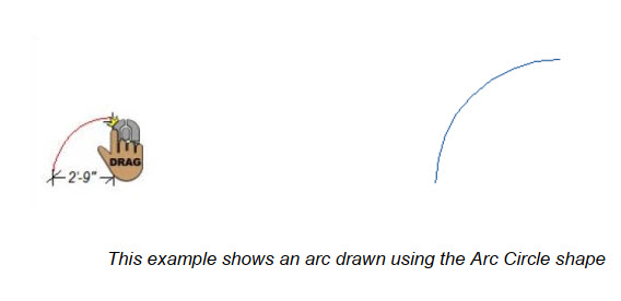
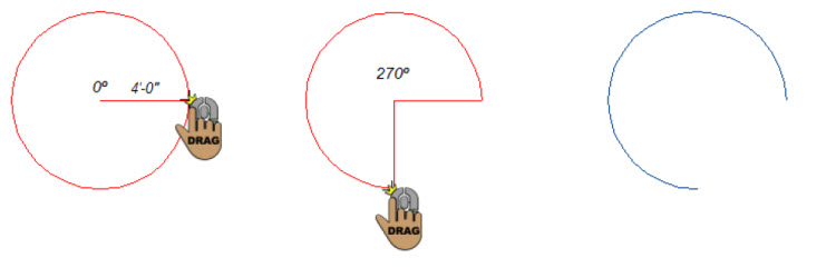
Drawing Circular Arcs
With FloorPlan Home Design Software, you can draw arcs that can be easily converted into curved walls, edging, stairs, and so on.
To draw a circular arc
1 Choose the Circular Arc  button from the Detail Tools group.
2 Use the Drag-to-Size drawing method to define the radius and then drag to specify the angle. Release to place.
Drawing Multigons
You can draw equal-sided decks, floors, even treehouses with the easy-to-use Multigon button and the Convert To feature. Before you draw, enter the number of sides you want for the multigon on the Properties pane in the sidebar. Be sure to press Return to accept new values.
To draw a multigon
1 Choose the Multigon  button from the Detail Tools group.
2 On the Properties pane, enter the number of sides for the shape and then press Return.
3 Use the Drag-to-Size drawing method to set the size for the multigon.
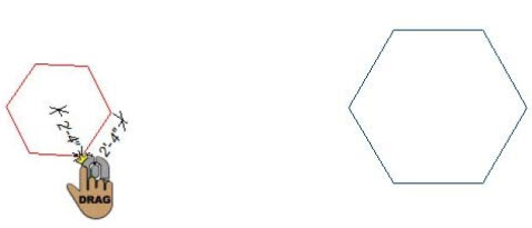
Note: To change the multigon’s size, but constrain its orientation, hold down the Command key while drawing.
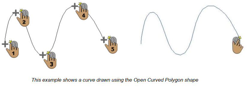
Drawing Curves
You can draw intricate curved flowerbeds and walls, among many other things, using the Curve Tool and the Convert To feature of FloorPlan Home Design Software. Before you draw, you can choose how you want to draw the shape on the Properties pane in the right sidebar.
To draw a curve
1 Choose the Curve  button from the Detail Tools group.
2 On the Properties pane, choose how you want to draw the shape.
3 In the design window, click to set the start point and drag to define the length and angle of the polylines.
4 Continue to click points and drag to define the shape of the curve and then right-click to place.
Callout
Allows you to define portions of the building model as details, sections, and elevations. The Callout size automatically adjusts to fit the text.
To draw Callout 
1. On the Detail plan toolbar, click the Callout Tool.
2. Use the Click-and-Drag drawing method to set the angle and length for the shape.
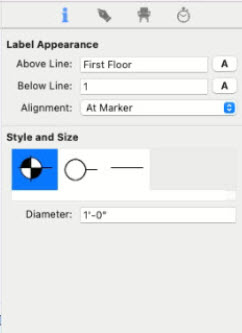
Callout Properties
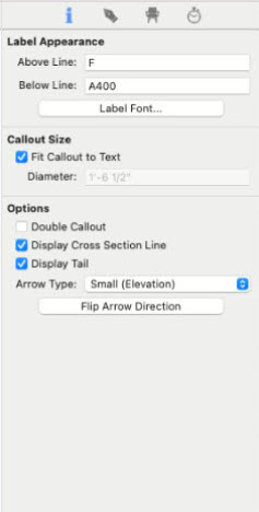
- You can add text in the above line or below the line text box.
- You can change the size and style of the font by clicking the font button. You can fit the text or add a custom size
- The double Callout check box will allow you to have a callout icon on both edges.
- You can Display cross-section lines and tails by clicking their check-box.
- You can flip its direction or change the size of arrows by using this properties tab
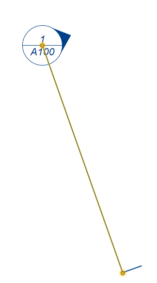
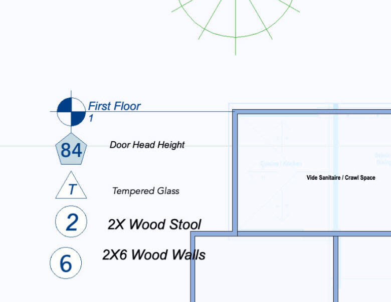
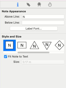
Note Markers
Add markers to identify building specifications such as framing requirements, pier locations, etc. Marker size automatically adjusts to fit the text. Variety of marker shapes available.
To Draw Note Marker 
1- On the Detail plan toolbar, click the Note Marker.
2- Use the Click Once to Place Drawing method to place the Note Marker in your design.
Marker Properties
- You can add text in the above line or below the line text box. Font size and style can be changed from the Font button
- You can change the shape of the Marker by clicking on the shape drop-down button.
- You can change the size of the text in marker or fit text in a marker by using fit text check-box
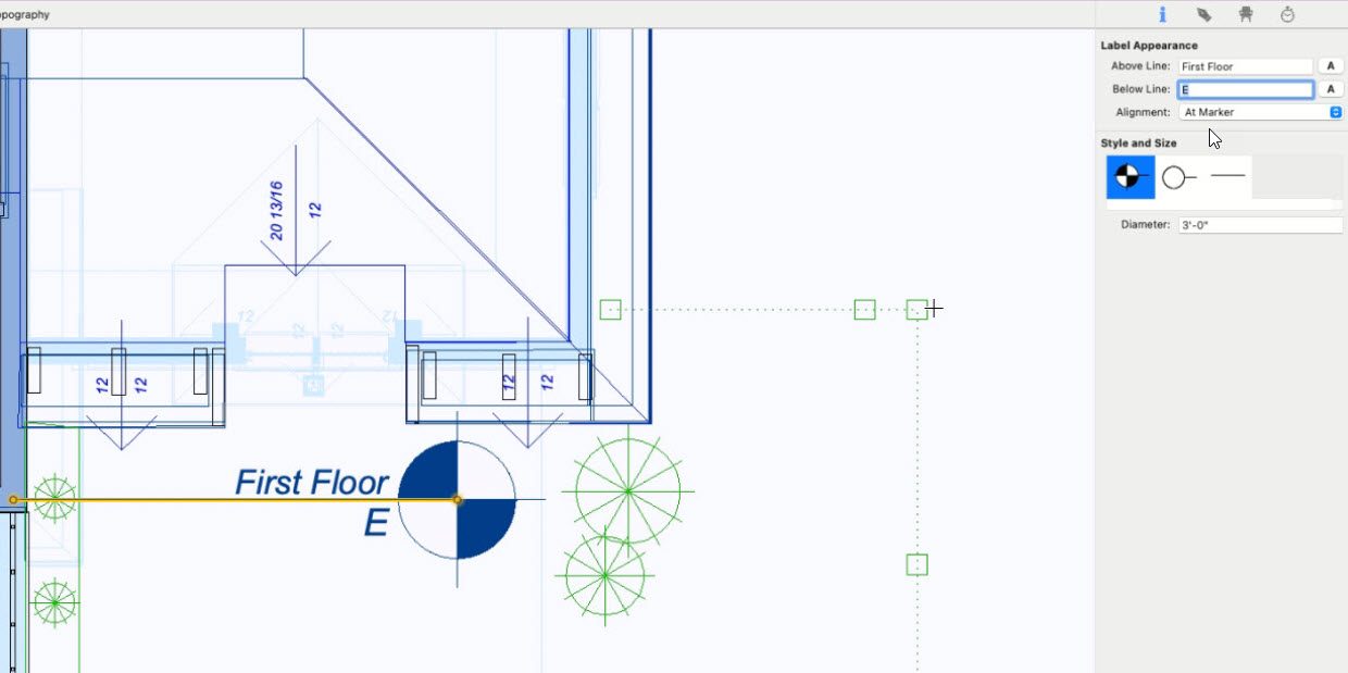
Marker Line
Add labels to drawing to callout important structural elevations when creating construction documentation.
To Draw Marker Line
- On the Detail plan toolbar, click the Marker Line
- Use the Click-and-Drag drawing method to set the angle and length for the shape.

Properties of Marker Line
- You can add text in the above line or below the line text box. Font type and size can be changed from the Font button.
- You can change the alignment of the marker to different points.
- You can change the shape of the Marker by clicking on the shape drop-down button.
- You can change the size of the text in marker or fit text in a marker by using fit text check-box
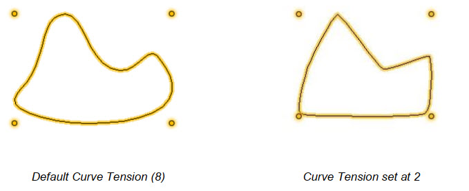
Changing Curve Tension
To further control the look of the shapes drawn with any of the arc or curve tools, you have control over the degree of curve assigned to them. With the Straighten feature, it is easy to create angular shapes and, with Curve Tension, you can change the appearance. Curve Tension is measured between 1 and 10. Specifying 1 in the dialog results in very little tension being applied, while specifying 10 causes a slightly-exaggerated curve.
To change curve tension
1 Choose the Select Objects  button from the Editing Tools group then click to select an element. Its properties appear on the Properties pane.
2 On the Properties pane, click the Adjust Curvature button. A dialog appears.
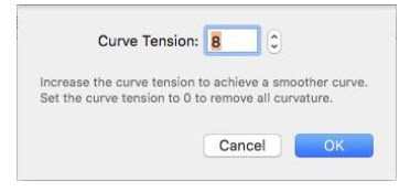
3 Enter the amount of Curve Tension that you want or click the arrow buttons to increase or decrease incrementally, then click OK.
To straighten a segment, enter 0 for curve tension.
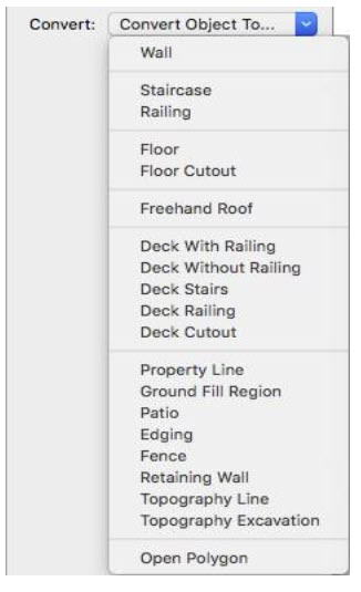
Converting Details to Intelligent Features
With FloorPlan Home Design Software, you can draw items that will appear only in the 2D design window, or you can convert them to intelligent elements. For example, you can convert a line to a fence, a rectangle to four exterior walls, a circle to a deck or even a circular stairway, and so on. There is virtually no limit to what you can draw, using this combination.
To convert a shape to an intelligent object
1 Choose the Select Objects button from the Editing Tools group then click to select the shape you want to edit.
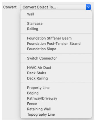
2 On the Properties pane, click the Convert drop-down menu and choose the feature you want the selection converted to.
To convert a line to an intelligent object
1 Choose the Select Objects button from the Editing Tools group then click to select the line you want to edit.
2 On the Properties pane, click the Convert drop-down menu and choose the feature you want the selection converted to.
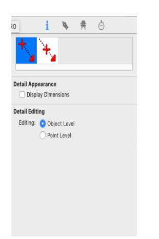
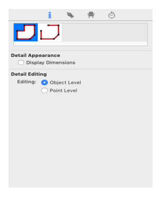
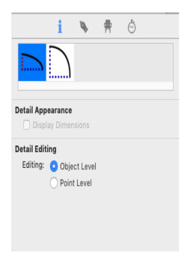
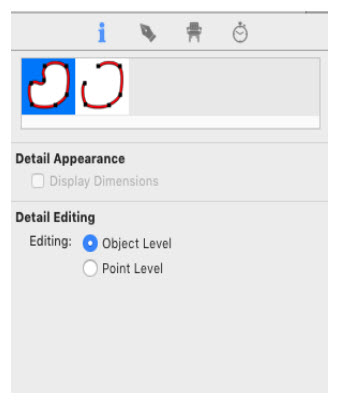
To Editing Detail Shapes
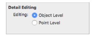
Object Level Editing is active by default. Object Level Editing, along with Point Level Editing, controls how your edits impact your object. When Object-Level is enabled, the entire object is selected; this is ideal for resizing an entire object. When Point Level is enabled, each control point on the object is selected; this is ideal for precision editing such as reshaping.

To fine-tune your design further, use the Add Point or Remove Point tools. These tools are available anytime but are especially useful when editing shapes.
To choose the edit level
1 Choose the Select Objects button from the Editing Tools group then click to select the shape you want to edit.
2 Click the Properties tab in the right sidebar and, under Detail Editing, choose Object Level or Point Level.
3 Drag a point to resize or reshape the selection.
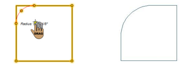
To fillet (round) a corner
Use the Fillet Corner Tool to create a round corner on an otherwise angled corner point. This allows you to manually set the curvature of a selected point.
1 Choose the Fillet Corner button from the Editing Tools group and then click to select the corner point you want to fillet.
2 Click the Properties tab in the right sidebar and choose Point Level editing.
3 Drag a corner point; hold down the mouse button and move the pointer toward the center of the element to define the curve you want.
4 Release the mouse to stop filleting the corner.
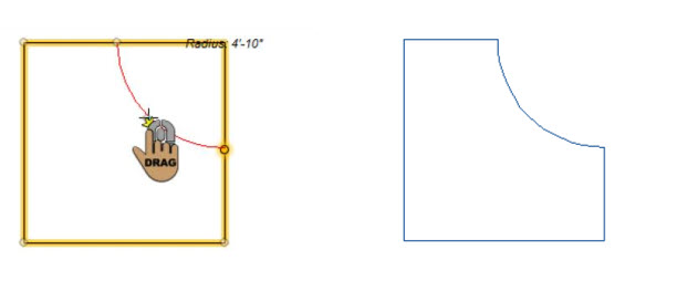
To inversely fillet a corner
You can use the Fillet Corner Tool to create an inverted round corner on an otherwise angled corner point. This allows you to manually set the curvature of a selected point.
1 Choose the Fillet Corner button from the Editing Tools group and then click to select the corner point you want to fillet.
2 Click the Properties tab in the right sidebar and choose Point Level editing.
3 Drag a corner point; hold down the mouse button and move the pointer toward the center of the element to define the curve you want.
4 Press and hold the Shift key to invert the fillet. The radius appears as you drag.
5 Release the mouse to stop filleting the corner, then release the Shift key.
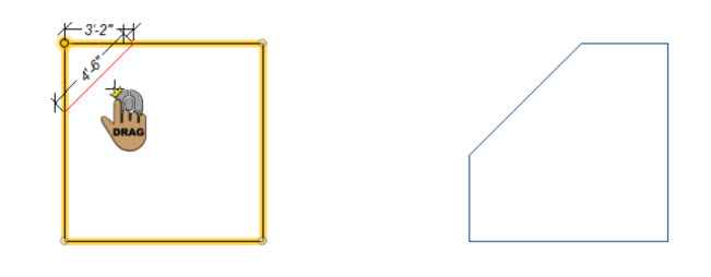
To chamfer a corner
Use the Chamfer Corner Tool to create a straight edge where an angled corner point exists.
1 Choose the Chamfer Corner button from the Editing Tools group and then click to select the corner point you want to chamfer.
2 Click the Properties tab in the right sidebar and choose Point Level editing.
3 Drag the point; hold down the mouse button and move the pointer toward the center of the object.
4 Release the mouse to stop chamfering the corner.
To add additional points
1 Choose the Add Point  button from the Editing Tools group. All of the points in your design are selected.
2 Position the crosshair where you want the point and click to add the point.
To remove a point
1 Choose the Remove Point  button from the Editing Tools group. All of the points in your design are selected.
2 Click the point you want to remove.
Filling a Shape with Plants
You can fill a 2D shape or line with plants, or place a row of plants using a line or curve. In the example below, a curve has been filled with an Iris using the perimeter option.
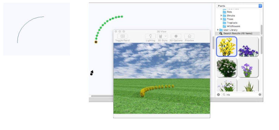
Note: Plants are added to the plan you are currently working on.
To fill a shape with plants
1 Draw the shape you want to fill with plants.
2 Choose the plant you want to add in the shape (for information on accessing plants, see Plants Libraries).
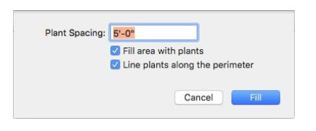
3 Right-click an edge of the shape and choose to Fill with Plants. A dialog appears.
4 Choose the settings you want and then click Fill