Control 3D Options
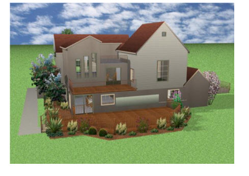
FloorPlan Home Design Software lets you view your design in photo-realistic 3D. You can select exterior and interior wall color, add realistic roof materials and select from a variety of wood textures to make your design completely unique. In the 3D View window, you can view your design from a variety of angles. Using Decorator Palettes, you can easily make changes to your decorating theme. This makes it easy to experiment with a variety of color schemes, both inside and outside your design, before picking up a paintbrush! With the powerful ClearView feature, you can literally see through the walls and view electrical, plumbing, and so on.
FloorPlan integrates the exclusive, patented RealModel® technology, making it easy to construct an actual scale model of any home you draw. Once you have completed your home design, details are automatically transferred to RealModel. Instructions on building your home model are printed, with numbered sections and floor plan templates that make assembly simple. This hands-on model shows you how to improve your design and save on construction costs before you break ground. This is the perfect tool for presenting your ideas to your builder or architect.
Moving Around in 3D
FloorPlan provides two interactive 3D viewing options, the 3D Walkthrough, and Fly-Around views, as well as an overhead aerial view and a room view, to focus on selected rooms in the design. Using interactive viewing, you can vary the viewing level by adjusting the altitude and height. Viewing speed and camera angle can also be adjusted to provide the best viewing capabilities available. The navigations tools are accessible from the 3D Tools group in the left sidebar when a 3D view is open.
Walkthrough Mode
Using 3D Walkthrough mode, you can navigate your design as if you were walking through it. You can navigate the exterior, walkthrough rooms, and even adjust the viewing elevation to change floors. The default walkthrough elevation is 5'-0". There are two ways to adjust the walkthrough elevation, which are described below.
To view your design using Walkthrough
1 Open a 3D View window and choose the Walkthrough  button from the 3D Tools group.
(alternatively) Choose 3D > 3D Navigation Method > Walkthrough.
2 In the 3D View, drag to navigate around your design; drag up to move inward, down to move outward.
To set your 3D viewpoint in 2D
You can adjust the walkthrough view in the 2D design window using the Viewpoint  icon. You may need to zoom out in the 2D view to find the Viewpoint icon initially.
1 Open the 3D Window View and choose the Walkthrough button so you can see both 2D and 3D.
2 In the 2D view, drag the Viewpoint icon center point to a new location in the design window to update the 3D view. Drag the arrow around the center point to rotate the view.
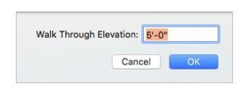
To change your Walkthrough elevation
■ In the 3D View, hold down the Control key while pressing the mouse button and drag up or down to raise or lower the elevation.
(alternatively) Choose 3D > 3D Navigation Method > Walkthrough and enter a new Walk Through Elevation then click OK.
(alternatively) Using two fingers on the trackpad, swipe up or down.
Fly Around Mode
Using Fly Around mode, you can navigate your design as if you were flying around it. This gives you a bird’s eye view of your exterior. You can even adjust the viewing elevation to get a closer look at some areas or see the bigger picture.
To view your design using Fly-Around
1 Open a 3D View window and choose the Fly Around  button from the 3D Tools group.
(alternatively) Choose 3D > 3D Navigation Method > Fly Around.
2 In the 3D View, drag to navigate around your design; dragging up and down changes your viewing angle, while dragging side-to-side navigates around the designated center of reference.
To specify a center of reference in Fly-Around mode
You can adjust the fly-around reference point in the 2D design window using the Center of Reference icon. You may need to zoom out in the 2D view to find the Center of Reference icon initially.
1 Open the 3D Window View and choose the Fly Around button so you can see both 2D and 3D.
2 In the 2D view, drag the Center of Reference  icon to specify the point that the view revolves around.
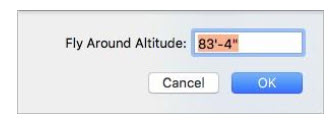
To change Fly-Around altitude
■ In the 3D View, hold down the Control key while pressing the mouse button and drag up or down to raise or lower the altitude.
(alternatively) Choose 3D > 3D Navigation Method > Fly-Around Altitude and enter a new FlyAround Altitude then click OK.
(alternatively) Press down with two fingers on the trackpad, and swipe up or down.
Aerial View Mode
This is a top-down view of your design. Use the Cutaway Slider to remove layers so you can see into your design. While viewing in aerial mode, you can pan the view and adjust your viewing altitude.
To see an aerial or bird’s eye view of your design
1 Open a 3D View window and choose the Aerial View  button from the 3D Tools group.
(alternatively) Choose 3D > 3D Navigation Method > Aerial View.
2 Drag to pan around the 3D View, or hold down the left mouse button and press the arrow keys to move the aerial view incrementally. To rotate around the designated center of reference, right-click and drag.
To specify a center of reference in Aerial mode
You can adjust the aerial reference point in the 2D design window using the Center of Reference icon. You may need to zoom out in the 2D view to find the Center of Reference icon initially.
1 Open the 3D Window View and choose the **Aerial View !button so you can see both 2D and 3D.
2 In the 2D view, drag the Center of Reference  icon to specify the point of view.
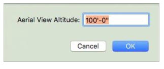
To change your aerial view altitude
■ In the 3D View, hold down the Control key while pressing the mouse button and drag up or down to raise or lower the altitude.
(alternatively) Choose 3D > 3D Navigation Method > Aerial View Altitude and enter the Aerial View Altitude then click OK.
(alternatively) Using two fingers on the trackpad, swipe up or down.
Room View Mode
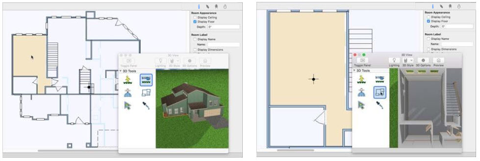
Using Room View, you can choose a room or space in 2D that you want to view in 3D. Once the view appears you can navigate and adjust the viewing altitude.
To see a room view of your design
1 Open a 3D View window so you can see the 2D and 3D views.
2 In the design window, click to select the room(s) you want to view. You can use the Select Objects tool in the 2D or 3D view.
Note: Press and hold Shift while clicking to select multiple rooms in 2D.
3 Click the Room View  button from the 3D Tools group. The 2D and 3D views are updated to focus on the selected room(s).
(alternatively) Choose 3D > 3D Navigation Method > Room View.
You can navigate the 3D view using your mouse
■ Drag to pan.
■ Right-click and drag to rotate.
■ Use the wheel on your mouse to adjust your viewing elevation.
Setting Navigation Options
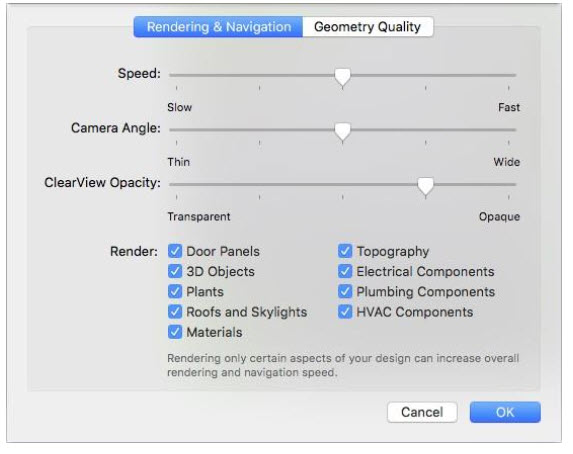
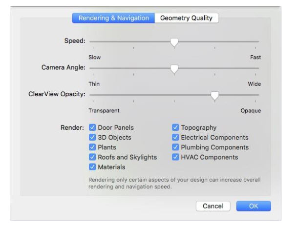
You can control the speed and the camera viewing angle as you navigate in 3D. These settings are available from the 3D view window or from the 3D menu. The Speed slider controls the 3D navigation speed; drag the slider to decrease or increase the speed. The faster the viewing speed, the lower the quality of the rendered 3D image. The Camera Angle slider controls how thin or wide the camera angle appears when viewing in 3D.
To adjust navigation options
1 Open a 3D view and click the 3D Options  button on the toolbar.
(alternatively) Choose 3D > Rendering Options.
2 Click the Rendering & Navigation tab, then adjust the Speed and Camera Angle settings, and then click OK.
Accessing the 3D Rendering Styles
With FloorPlan’s five 3D rendering options you can view your design in a variety of ways. You can access the rendering styles from the 3D view toolbar or the 3D menu.
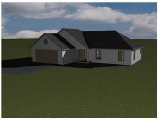
Shaded texture  shows all of the paint, material, objects, and plants.
ClearView lets you see potential conflicts hidden by walls, for example, between utilities, and so on.
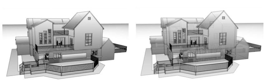
The ClearView Opacity is controlled by the Rendering & Navigation options, which you can access from the 3D view window toolbar or from the 3D menu. Drag the slider to control how transparent or opaque the view appears.
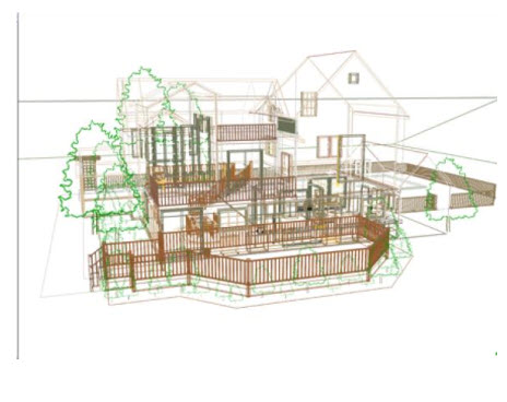
Colored Wireframe mode displays your design on a white background. Each feature of your floor plan will be rendered in the color of the plan tab where it is drawn. For example, walls will be displayed in the color you have defined for the Floor Plan.
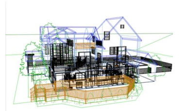
Textured Wireframe  mode also displays your design on a white background. But, each feature of your floor plan will be rendered in the color of the material you have applied to it.
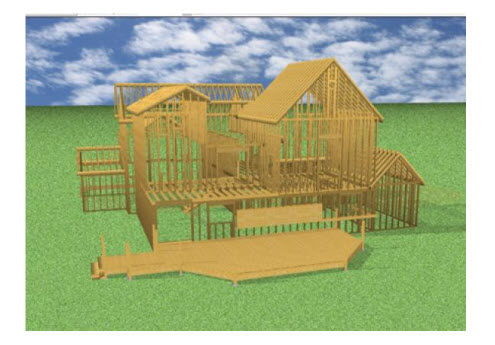
Framing  mode displays your design to show the studs, rafters, and other framing features. Wall attachments such as plumbing and electrical components are not visible while in framing mode.
 Accessing the Photo-Realistic Rendering Styles
There are six Photo-realistic rendering styles available. To access the Photo-Realistic rendering styles, be sure Photo-Realistic Rendering mode is activated.

Hatch the hatch style produces an effect similar to a shaded pencil drawing. The image is made up of a series of pencil “strokes” all in a similar orientation. All of the strokes are to provide shading - no lines are drawn.