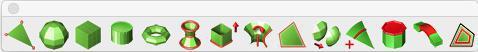
Mesh Modeling
Quad mesh modeling tools allow you to create models that can be quickly pushed or pulled into complex shapes. These tools create quad meshes, which are suitable for use with subdivision modeling techniques.
Meshes are drawn and edited with a polygon control cage. You can subdivide the mesh to increase or decrease the level of smoothness and adjust the availability of quads, which can be edited using the Deep Select tool and Gripper. Mesh properties are available in the Inspector (on the Data tab), where you can view the vertex count, facet count, and edit the sub-division level.
- Once a mesh model has been created, users can:
- Print a 3D model using stereolithgraphy.
- Share data with subdivision applications using OBJ and DWG.
- Use the Edit Convert command to change into a precision solid.
Points Mesh
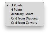
The Points Mesh tool creates a planar mesh from the following methods: 3 Points, 4 Points, Arbitrary Points, and Grid. After the tool is selected, the options drop-down becomes available in the Prompt Window.
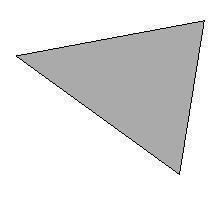
3 Points
This option creates a planar mesh based on three user-defined points.
Creating a 3 Points Mesh
- Select the Point mesh tool from the toolbar.
- On the Prompt Window, choose 3 Points from the Method drop-•down.
- Click three points to define the shape.
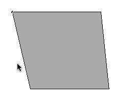
4 Points
This option creates a planar mesh based on four user-defined points.
Creating a 4 Points Mesh
- Select the Point mesh tool from the toolbar.
- On the Prompt Window, choose 4 Points from the Method drop-•down.
- Click four points to define the shape.
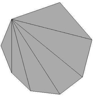
Arbitrary Points
This option creates a mesh based on the number and position of points defined by the user. The number facets and vertices depend on the number of user-defined points.
Creating an Arbitrary Point Mesh
- Select the Point mesh tool from the toolbar.
- On the Prompt Window, choose Arbitrary from the Method drop-•down.
- Click the desired number of points to define the shape and right-•click (or double-•click) to finish.
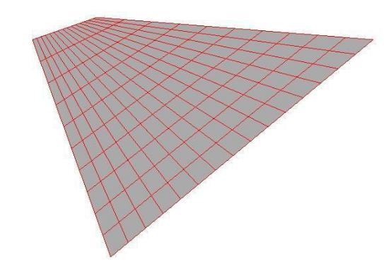
Grid from Diagonal
This option creates a mesh grid based on two diagonal user-defined points. The number of equally-sized grid blocks is determined based on the M and N values on the Prompt Window. You can specify the number of blocks before or after you define the mesh. The M value defines the number of horizontal blocks, while the N value defines the number of vertical blocks.
Creating a Diagonal Grid Mesh
- Select the Point mesh tool from the toolbar.
- On the Prompt Window, choose Grid from Diagonal the Method drop-•down.
- (optional) Enter the number of horizontal blocks in the M text field and the number of vertical blocks in the N text field, pressing the Enter key after each entry.
- Click to set the start point for the grid mesh.
- Drag your cursor, diagonally, and click to set the end point for the grid mesh. The mesh appears. You can edit the M and N values, if needed.
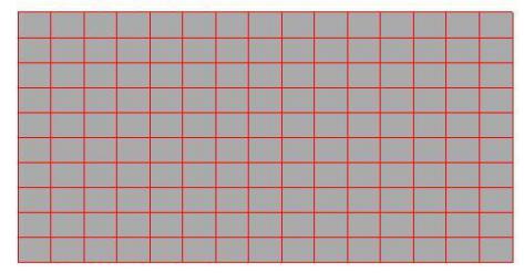
Grid from Corners
This option creates a mesh grid based on four user-defined points. The number of equally-sized grid blocks is determined based on the M and N values on the Prompt Window. You can specify the number of blocks before or after you define the mesh. The M value defines the number of horizontal blocks, while the N value defines the number of vertical blocks.
Creating a Corner Grid Mesh
- Select the Point mesh tool from the toolbar.
- On the Prompt Window, choose Grid from Corners the Method drop-•down.
- (optional) Enter the number of horizontal blocks in the M text field and the number of vertical blocks in the N text field, pressing the Enter key after each entry.
- Click to set the four corner points for the grid mesh. The mesh appears. You can edit the M and N values, if needed.
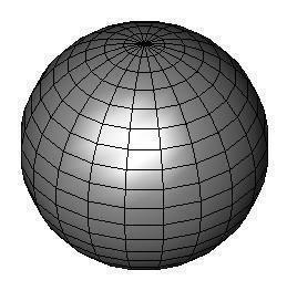
Sphere
The Sphere Mesh tool creates a sphere of quads based on two user-defined points. The grid is defined by the number of rings and sectors. Rings circle the Z axis, horizontally, from north to south. while sectors wrap vertically around the Z axis. Both values can be defined on the Prompt Window before or after the mesh is created.
Creating a Sphere Mesh
- Select the Sphere mesh tool from the toolbar.
- (optional) Enter a value in the # Rings field to specify the number of horizontal rings to wrap around the shape, and enter a value in the # Sectors field to specify the number of vertical sectors to wrap around the shape. Be sure to press the Enter key after each entry.
- Click to set the center point for the sphere.
- Drag to the desired distance and then click to set the radius for the sphere. The mesh appears. You can edit the Radius, # Rings, or # Sectors values, if needed.
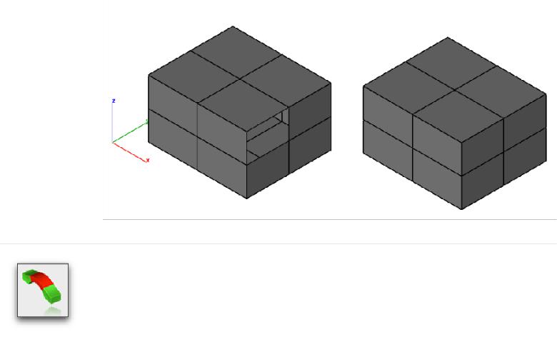
Block
The Block Mesh tool creates a block made up of six quad meshes based on diagonal user-defined points and a user-defined height. The number of grid blocks is determined based on the #X, #Y, and #Z values on the Prompt Window. You can specify the number of block before or after you define the mesh. The #X value defines the number of blocks along the X axis, the #Y value defines the number of blocks along the Y axis, and the #Z value defines the number of blocks along the Z axis.
Creating a Block Mesh
- Select the Block mesh tool from the toolbar.
- (optional) Enter a value in the #X, #Y, or #Z fields to specify the number of blocks along the corresponding axis. Be sure to press the Enter key after each entry.
- Click to set the start point for the grid mesh.
- Drag your cursor, diagonally, and click to set the end point for the grid mesh.
- Drag along the Z axis and click to set the height for the mesh. The mesh appears. You can edit the # fields or Length, Width, or Height values, if needed.

Torus
The Torus Mesh tool creates a torus of mesh quads based two user-defined points. The mesh is defined by the number of rings and sectors. Rings wrap around the Z axis, while sectors wrap around each ring. Both values can be defined on the Prompt Window before or after
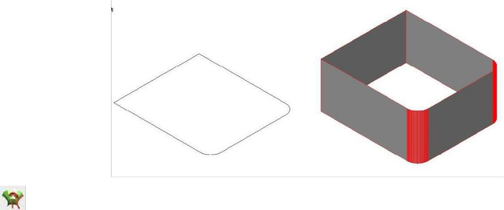
Extrude
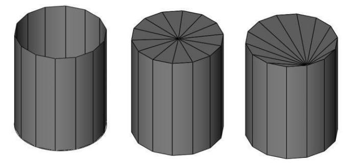
The Extrude Mesh tool creates a collection of quad meshes extruded from a planar set of curves. The number of segments that wrap around the center of the curves is determined based on the N value on the Prompt Window. The value can be defined before or after the mesh is created.
Creating an Extruded Mesh
- Select the Extrude mesh tool from the toolbar.
- Enter a value in the N field to specify the number of sections. Be sure to press the Enter key to accept the value.
- Select the object to be used for the mesh.
- Click two points to specify the length and direction for the extrusion. The mesh appears. You can edit the dX, dY, or dZ values, if needed.
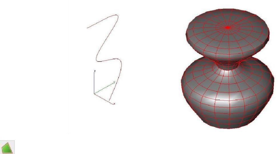
Lathe
The Lathe Mesh tool creates a mesh curve around a user-defined axis. The mesh is defined by the number of rings and sections, and the angle of the mesh. Rings circle the axis, from north to south while sections wrap vertically around the axis. The angle determines the degree the mesh wraps around the axis (an angle of 360, for example, wraps the entire axis). All values can be defined on the Prompt Window before or after the mesh is created.
Creating a Lathe Mesh
- Select the Lathe mesh tool from the toolbar.
- (optional) Enter the number of rings, sections, and angle for the lathe on the Prompt Window and then press Enter to accept the value.
- Select the object to be used for the mesh.
- Click two points to define the lathe axis. The mesh appears. You can edit the Rings, Sections, or Angle values, if needed.
Cover
The Cover Mesh tool creates a mesh surface based on planar or non-planar curves or lines. The cover surface depends on the user-defined edge length, which can be specified on the Prompt Window before or after the mesh is created (the edge length is used only as an approximate length for facet edges). The Cover Mesh attempts to create quad meshes everywhere except on boundary edges, where it creates triangles.
Creating a Cover Mesh
- Select the Cover mesh tool from the toolbar.
- (optional) Enter the Edge Length value on the Prompt Window and then press Enter to accept the value.
- Select the object to be used for the mesh. The mesh appears. You can edit the Edge Length value, if needed.
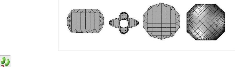
Subdivision
The Subdivision tool specifies the level of mesh subdivisions, adding vertices and surfaces to increase smoothness. The tool allows you to click to incrementally increases the level of tool is activated, you can click a mesh to incrementally increase the level of subdivisions. You can also control the SubD level value in the Inspector. There are two subdivision methods available in the Prompt Window:
Faceted- smoothes the mesh by subdividing the quads incrementally by three facets Catmull-Clark- an algorithm that subdivides the existing faces and edges to smooth the quads
Subdividing a mesh
- Click the Subdivision tool from the toolbar.
- On the Prompt Window, choose the Faceted or Catmull-•Clark method.
- Click to select the mesh you want to subdivide.
- Continue to click to increase the subdivisions to the level you want. The mesh is updated.
Editing a subdivision
- Click the Selection tool from the main toolbar.
- Select the subdivided mesh you want to edit. The object properties appear on the
Inspector’s Data tab.
- Enter the subdivision level you want in the SubD Level field and click Apply. The mesh is updated.
Viewing a mesh subdivision
When viewing the Control Mesh, right-•click (Control-•click) the mesh and choose Show Subdivision from the submenu.
When viewing the subdivision, choose Show Subdivision from the submenu to see the subdivision levels.
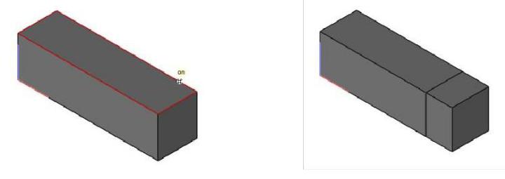
Add Loop
The Add Loop tool inserts a row of facets at a user defined location.
Using Add Loop
- Select the Add Loop mesh tool from the toolbar.
- Select the mesh facet that will contain the new loop.
- Enter location along one of the mesh edges for the new loop.
Fill Hole
The Fill Hole tool adds triangles or quads to close an open hole.
The Options button in the data entry window to specify addition options such as Converting to Quads and Add Center Point.
The Add Center Point option will insert a vertex at the approximate center of the hole with facets sharing the center point.
Using Fill Hole
- Select the Fill Hole tool from the Mesh tool palette.
- Select the mesh edge to close.
Bridge
The Bridge tool connects two facet regions together.
Using the Bridge Tool
- Select the Bride tool from the Mesh tool palette.
- Select the facet for bridge start.
- Select the facet for bridge to end.
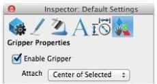
Gripper and Mesh Modeling
The Gripper provides additional features for modifying a mesh as described below.
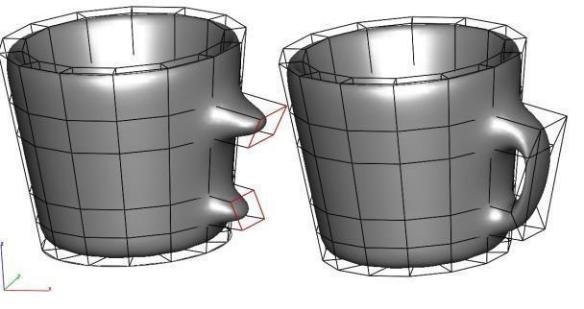
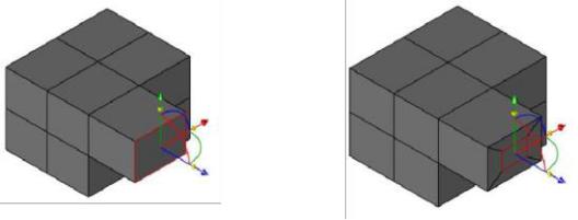
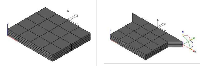
•Dynamic Extrude
Use the Deep Select Tool to select a facet. Position mouse over one of the translation arrow icons of the Gripper and then Press either Option (Mac) or Control (Windows) and drag the face away to dynamically extrude a new set of facets.
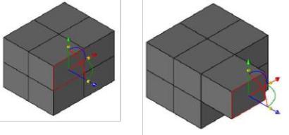
1. Dynamic Scale Copy
Use the Deep Select Tool to select a facet. Position the mouse of the scale icons of the Gripper and Press either Option (Mac) or Control (Window) to create a new set of facets scaled to the original selected facet.
1. Mesh Symmetry via WorkPlane
Modifying a mesh with symmetry is possible by enabling the “Mesh
Symmetry via Workplane” option located in the Inspector Gripper Properties.
The symmetry plane is defined by setting the WorkPlane origin and X Axis.
Vertices and facets modified by the Gripper will automatically modify symmetrical vertices and faces. When enabled, the Add Loop and Dynamic Extrusion tools also reflect symmetrical modifications to the mesh.