File
When launching ViaCAD from an icon, an empty drawing file called “untitled” is created. You can immediately start creating and modifying objects in your untitled drawing or you may load a preexisting drawing. Saving and retrieving files are performed with the File command located in the Menu Bar. This chapter covers the saving, retrieving, and other commands located in the File Menu.
File Menu
The File menu lists commands used to read/write files to disk, print, and the command to quit or exit
ViaCAD. A description of each option follows:
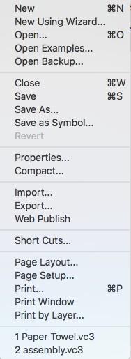
New
The new command will create and initialize a blank drawing. The default drawing title is labeled “untitled”. Previously created drawings will stay open until specifically closed or until the designer quits the program.
New Using Wizard
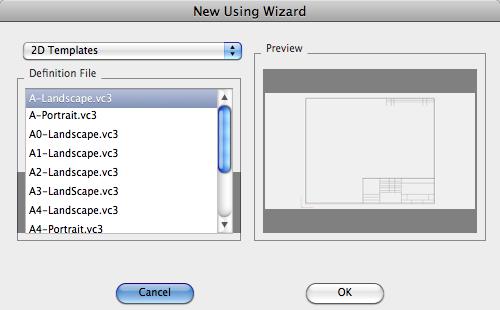
The New Using Wizard dialog box provides the ability to create a new drawing file from a collection of custom settings or selection of an existing file from a template. Click the default button to use the same settings used in the New command.
2D Template
Templates are existing files with predefined drawing and title blocks. A variety are provided to handle the major drawing formats. You can add additional templates to the drop-down menu by adding files to the Templates/2D folder, located in the Applications folder.
Custom Drawing
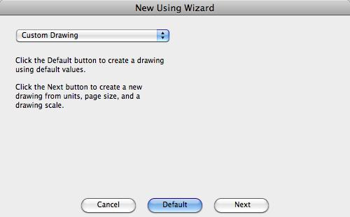
The Custom Drawing option allows you to specify a variety of settings used to set up the drawing. These settings include Unit Format, Printer Paper Size, Drawing Size, Drawing Scale, and Annotation Set
Unit Format
Specifies the unit type for the drawing from a drop-down menu consisting of metric and imperial unit formats.
Printer Paper Size
Select the page orientation or paper size from the associated drop-down menus. If the size is larger than the available printer size, tiled printing will automatically turn on. The width and height of the page are displayed as a reference.
Select the Show Page Breaks in Drawing Window option to distinguish the page boundaries on the drawing window.
Drawing Scale
Select a drawing scale from either engineering, architectural or metric. Select the Custom option to define unique scales relating printer page output with the actual world size. These fields support expression parsing, which allows you to put in unit identifiers.
Examples include:
1"=1'
1cm = 1m
3/4" = 1'
Annotation Settings
Specify text height as a function of world size or printer size. The relation between the two is defined by the drawing scale. If you enter a text height defined by the printer page, the actual world size will scale accordingly.
Specify the dimension format used in the drawing from a variety of standard settings.
The Scale Dimension Values with Text Height checkbox adjusts the dimension properties such as arrow head size, extensions, gaps, and leaders based on the change in the dimension text size.
Open
To read an existing file use the Open command. The Open command will display a dialog box prompting the user to select the file format and name.

Open Examples…
Opens the example files provided along with this application.
Open Backup…
Opens files saved to the Backup folder. The Backup folder is the location of files saved using the Auto save command. Auto Save is enabled from the Preferences: Flinging options.
Close
This command will close the current file. If other files are open, they are left open. If the file has changed since opening, the user will be asked if they would like to save the existing file.
Save
The Save command will write the file into the most recently saved file. No dialog will appear, as it uses the previous save information for file name and location. If you need to save the file as a new name use the Save As command.
Save As
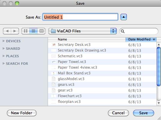
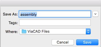
The Save As command will write the objects into a file specified by the user. A dialog box will appear that allows the specification of file name and folder location.
Save as symbol
The Save As command will write the objects into a file specified by the user. A dialog box will appear that allows the specification of file name and folder location.
Save for Review
The Save for Review command saves the current file to a new file name while locking the layer list. Locking the layer list prevents anyone from making changes to the file without first unlocking the layers. Use the Save for Review command in combination with the Markup tools.
Revert
The Revert command will restore the file to the last saved state. This command deletes all changes made in the drawing since the file open and is not undoable.
Properties
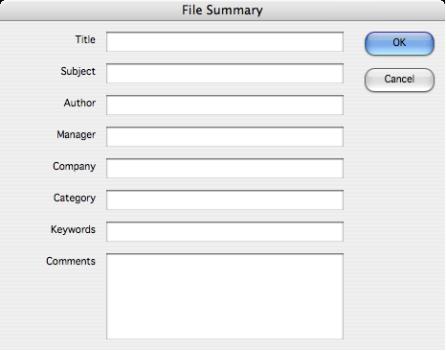
The File Properties dialog allows you to save information along with the file. By entering information in the text fields, you can identify the file with a title, subject, author name, keywords, and other important information about the file.
Compact
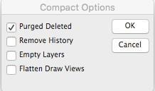
The File: Compact option allows you to remove temporary objects from the file, remove history, and empty the layers, compacting a file to its smallest size.
Reference Files
Reference Files are external files embedded into a drawing while maintaining a link to the original file enabling updates. Advantages of Reference Files are:
Smaller file sizes
Provides a means for many users to work on individual components of a large project
Reference Files can be updated, added, edited at any time
Tools for creating and managing Reference Files are located under the File. The submenu has four options.
Attach
Specify a file to be referenced. This is the first step in linking another drawing to your current drawing. Any file type supported by the application can be attached, including DWG, SAT, STEP, PDF, ViaCAD or Shark files.
Reference Manager
A dialog box providing additional tools to manage references. The Reference Manager dialog provides tools for updating, detaching, replacing, and editing reference files.
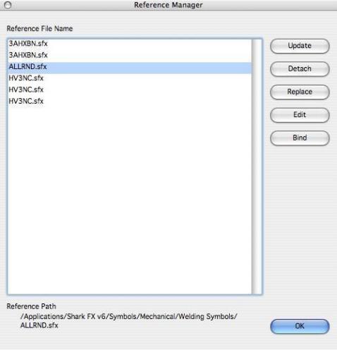
Update - Updates the selected reference file. This will reload the file from disk into the file.
Detach - Removes the selected reference by removing the reference and the geometry from the file.
Replace - Replaces the selected reference file with another reference file.
Edit - Reads the selected reference file into a new drawing window for editing.
Bind - Removes the link to the reference file, but leaves the geometry in the file.
Update All - Update all references in the file.
Set Attach Point-Assigns an attachment point for a drawing. This attachment point is used if this file is later used as a reference file.