Constraint
Dimension and constraint tools are available to help manage the geometric relationships between 2D shapes. These relationships are used to remember design intent of 2D sketches, which typically drive 3D solids. Modifying any object within a system of constraints will update all other dependent objects accordingly.
The Constraints tool palette contains a variety of constraint types, including distance, radius, diameter, coincident, tangent, horizontal, vertical, perpendicular, offset, concentric, parallel, equal, collinear, and symmetry.

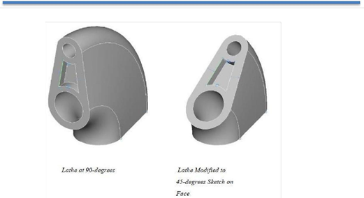
Sketches may also be defined on a face of a solid. In this situation, the sketch is dependent on the geometry of the face and updates as the face changes. This includes the ability for the sketch to change its orientation to match any changes of the face orientation.
Smart Dimension
This tool creates a user-defined distance constraint.
Using the Dimension tool
- Click the Dimension tool on the Constraints tool palette.
- Click on a 2D shape to start the dimension.
- Drag your cursor in the direction you want the dimension placed.
- Click again to place the dimension.
Auto Constraints
This tool automatically applies constraints to user-defined curves and dimensions. This is particularly useful when working with shapes and objects created using a different drawing tool. This tool adds the following constraints to selected objects:
- Vertical
- Horizontal Tangent
- Perpendicular Concentric
- Coincident Equal
- Smart Dimensions
Using the Auto Constraints tool
- Click the Auto Constraint tool on the Constraints tool palette.
- Click the objects you want to constraint.
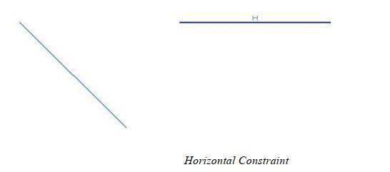
Horizontal Constraint
This tool adds a horizontal constraint to a line. You can select one or more-line segments to apply the constraint. Horizontal is defined by the x-axis.
Using the Horizontal tool (Method 1)
- Click the Horizontal tool on the Constraints tool palette.
- Click one or more lines to constrain horizontally.
The tool tip line has an option to make selected points horizontal. Use this option to constrain selected points on an object instead of the entire object. The below example constrains the center point of a circle.
Using the Horizontal Constraint tool (Method 2)
- Click on the Horizontal Constraints tool.
- Hold down the Option key (CTRL for PC).
- Click the first object.
- Click point on object to constrain.
- Click second object.
- Click point on object to constrain.
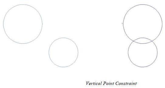
Vertical Constraint
This tool adds a vertical constraint to a line. You can select one or more-line segments to apply the constraint. Vertical is defined by the y-axis.
Using the Vertical tool (Method 1)
- Click the Vertical tool on the Constraints tool palette.
- Click one or more lines to constrain vertically.
The tool tip line has an option to make selected points vertical. Use this option to constrain selected points on an object instead of the entire object. The below example constrains the center point of a circle.
Using the Vertical tool (Method 2)
- Click the Vertical tool.
- Hold down the Option key (CTRL for PC).
- Click the first object.
- Click point on object to constrain.
- Click the second object.
- Click point on object to constrain.
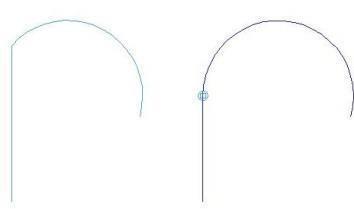
Coincident Constraint
This tool adds a coincident constraint between two or more objects.
Using the Coincident tool (Method 1)
- Click the Coincident tool on the Constraints tool palette.
- Click the first curve.
- Specify a location on the curve to constrain.
- Click the second curve to constrain.
- Specify a location on the curve to constrain.
Selecting a defining point will tie the constraint to this location. Selecting along a curve will preserve the parametric location (relative position along the curve).
Using the Coincident tool (Method 2)
- Click the Coincident tool on the Constraints tool palette.
- Click two or more objects to constrain. All shared endpoints with a tolerance are automatically constrained.
Tangent Constraint
This tool adds a tangent constraint to two or more curves.
Using the Tangent tool (Method 1)
- Click the Tangent tool on the Constraints tool palette.
- Click the first curve near the shared tangent location.
- Click the second curve near the shared tangent location.
Using the Tangent tool (Method2)
- Click the Tangent tool on the Constraints tool palette.
- Click two or more objects to tangent constrain.
The latter method will automatically add tangent constraints to curves that are within a distance and angular tolerance.
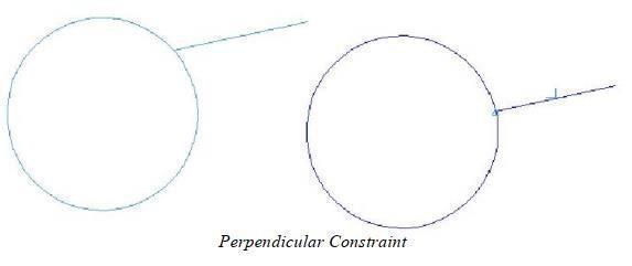
Perpendicular Constraint
This tool adds a normal constraint between a line and a curve.
Using the Perpendicular tool
- Click the Perpendicular tool on the Constraints tool palette.
- Click one or more objects to constrain.
Offset Constraint
This tool adds an offset constraint between two objects. The offset distance can be set on the Data Entry window.
Using the Offset tool
- Click the Offset tool on the Constraints tool palette.
- Click one or more objects to constrain.
- (optional) Enter a new value in the Offset text field, on the Data Entry window.
Equal Constraint
This tool constrains two lines to be the same length or two circles the same radius.
Using the Equal tool
- Click the Equal tool on the Constraints tool palette
- Click one or more objects to constrain.
Locked Constraint
This tool locks a curve so it will not move. The constraint solver will not modify a locked curve in any manner.
Using the Locked tool
- Click the Fixed tool on the Constraints tool palette
- Click one or more objects to constrain.
Locked curves are displayed using the Locked Constraint Color defined in the File: Preferences:
Concentric Constraint
This tool makes two circles share the same Center Point
Using the Concentric tool
- Click the Concentric tool on the Constraints tool palette.
- Select two or more circles you want to share one Center Point.
Symmetric Constraint
This tool makes two curves symmetrical about a line.
Using the Symmetric tool
- Click the Symmetric tool on the Constraints tool palette.
- Select the symmetry reference line.
- Select the first curve.
- Select the second curve to complete the symmetrical constraint.
Midpoint Constraint
This tool creates a midpoint constraint between a curve (point, line, circle) and the midpoint of a reference line.
Using the Midpoint tool
Click the Midpoint tool on the Constraints tool palette
Click one or more objects to constraint
Collinear Constraint
This tool makes two lines collinear or lie in a straight line.
Using the Collinear tool
Click the Collinear tool on the Constraints tool palette
Click one or more objects to constrain.
Animating Dimensions
This tool animates a sketch by modifying a dimension value through a range of values. If you animate a sketch while in sketch mode, only the sketch is updated. If you animate a sketch outside of the sketch mode, dependent surfaces and solids update accordingly.
Using the Animate tool
Select a dimension
Click the Animate tool on the Constraints tool palette. The DCM Animation Settings dialog appears.
Enter the start and ending values.
Enter the number of steps to use between the start and end values.
Click Play.
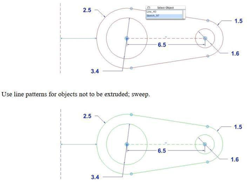
Under and Over Constrained Geometry
A major feature of the constraint management system is that it is designed to handle under and over constrained data in such a way that the user is helped to build a properly defined object interactively. Under-constrained data is defined as data having insufficient dimensions and logical constraints to define the geometry uniquely. The default under-constrained object color is blue. Over-constrained data is defined as data having too many or conflicting dimensions and legal constraints. The default over-constrained object color is dark yellow. The fully constrained object color is green.
Dimension Driven Geometry
Dimensions created in the sketch mode are, by default, driving dimensions. This means that changing the dimension value will force curves associated with the dimension to update to the new value. A dimension that is driven by the curve is called a reference dimension. Outside the sketch mode, dimensions created are reference dimensions. To change a dimension from driving to driven, right-click on a dimension.
Sketch Axis
To turn on a sketch axis, open the Concept Explorer and Ctrl-click on a sketch and toggle between turning the sketch axis on and off. Moving the sketch axis will move the entire sketch, and rotating the axis will rotate the sketch.
Variables/Equations
The Variables and Equations dialog allows you to create variables which may be constant or mathematical expressions. To access the dialog, to go Window: Variables/Equations.
As you create and assign dimension constraints to geometry, the equation dialog automatically updates with new entries. The Name field contains a unique identifier from the object. The Value field represents its current evaluation expression. The Equation field contains a string expression defining a mathematical relationship. The following types of variables within equations are supported:
A variable associated with a dimension.
A simple variable not associated with a dimension.Linear equations of the form a1v1+a2v2+a3*v3+...+c =0. Non-linear equations of the form f (v1, v2, v3) =0.
Sketch to 3D
 **
**
Sketching on Faces
ViaCAD supports the creation of sketches on the face of a solid. In this case, the sketch is dependent on the geometry of the face and updates as the face changes. This includes the ability for the sketch to change its orientation to match any changes of the face orientation.
Establishing a sketch on the face of a solid is accomplished by first setting the work plane to the face using the Work Plane: Set Objects command located in the menu bar. The orientation and origin for the work plane define the sketch axis when constraints on the face are applied. The sketch on face remains active until the work plane is changed by the user.
Face edges can be used as references for sketches. Since these edges are defined by the solid and cannot be changed, they are marked as “Locked”. Horizontal and vertical references are relative to the sketch x and y axis, respectivelyUse the “Distance” option for protrusions and cutouts to maintain a distance that is relative to face normal.
Adding and Removing Items from a Sketch
To remove a curve or dimension from a sketch, simply select the item and choose Edit: Cut. Curves or dimensions are automatically added to a sketch when they are used as part of a constraint involving the sketch.