Section Detailer
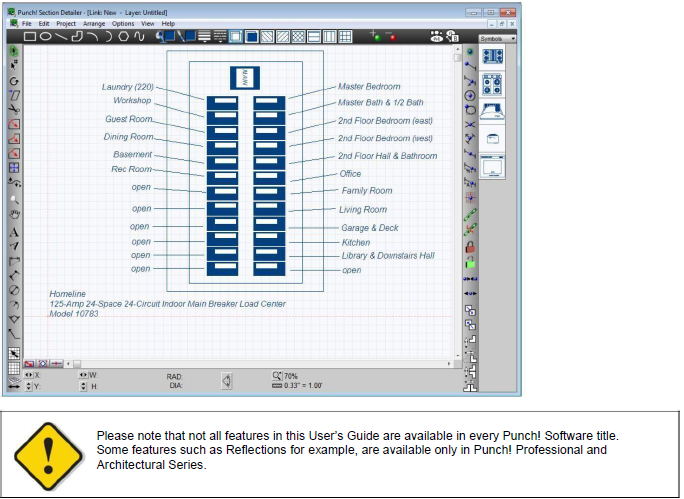
You can store even more details of your home design, without cluttering your project, using Section Detailer. Create a separate detailed drawing of built-in book shelving or an electrical sub-panel, then simply place a reference marker to the detail in your main project.
Launching Section Detailer
- Click Design menu > Launch PowerTool. The PowerTool Launcher is displayed.
-
Click to select Section Detailer and click the Launch button. The Section Detailer is launched and the Choose Detail window is displayed.
-
Choose the Style you want, type a name in the Detail Name text box, and choose the link size, then click OK.
- Use the drawing tools, text, and symbols to create your detail.
Managing Section Details
Section Detailer not only allows you to save Details for use in your 2D drawings, it also has easy-to-use tools for managing how those details are displayed in the 2D drawing.
To change a detail’s link properties 
-
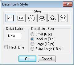
Click the Detail Properties button. The Detail Link Style dialog box appears. (alternatively) Click Project menu > Detail Link Properties.
-
Click one of the Styles to choose the detail link that will appear in your drawing.
-
Type a name in the Detail Name text box. This is limited to five characters.
-
Click a Detail Link Size to choose the size of the detail link that will appear in your drawing. (optional) Select the Thick Line checkbox to set the line weight in your detail drawing to thick.
- Click OK.
To open a new detail 
-
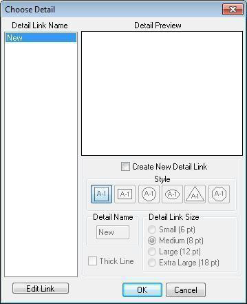
Click the Switch Working Detail button. The Choose Detail dialog box is displayed. (alternatively) Click Project menu > Switch Details.
-
Select the Create New Detail Link checkbox.
-
Click one of the Styles to choose the detail link that will appear in your drawing.
-
Type a name in the Detail Name text box. This is limited to five characters.
-
Click a Detail Link Size to choose the size of the detail link that will appear in your drawing.
To open an existing detail
-
Click the Switch Working Detail button. The Choose Detail dialog box is displayed. (alternatively) Click Project menu > Switch Details.
-
Under Detail Link Name, choose the name of the detail you want to open and then click OK.
Using 2D Drawing Tools to Draw Details
Section Detailer features a full array 2D CAD drawing and editing tools. You can create details from scratch with text or the drawing tools. Or you can create new details by adding CAD geometry to existing symbols.

Tip: When drawing multiple instances of a CAD component, be sure to turn off Auto Reset. When Auto Reset Tools is unchecked, you can draw concurrent CAD components without selecting the corresponding CAD tool each time. For more information, see “Controlling Drawing Settings”.
For more information on using drawing tools, see “Detail Plan Tab”.
Adding 2D Symbols to a Detail
You can use the contents of the Symbols libraries to create details. For information on navigating the Symbols libraries and adding them to your design, see in the section “2D Symbols Library”.
Using Rules and Fills
You can control the color and thickness (weight) of the lines or fills of the CAD shapes in your detail drawing.

For more information, see “Draw Style Tab”.
To set the fill to gradient
-
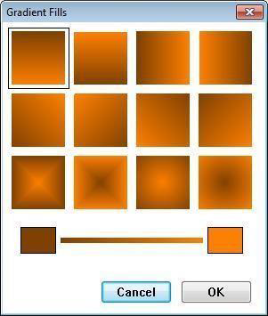
Click Options menu > Fill > Gradients. The Gradient Fills dialog box is displayed.
-
Click one of the gradient patterns to select it.
-
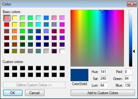
Click the dark color icon on the left side of the gradient display. The Color dialog box is displayed.
-
Click an area on the color spectrum window to select a color, then adjust the values, if necessary. (optional) Adjust the current Red, Green and Blue values to create a custom color.
-
Click OK to set the first color in the gradient.
-
Repeat steps 3 through 3 to set the second gradient color.
- Click OK.
Adding Text to Details

Use text to add information to your detail. For example, you might specify a model number or a specific feature in your detail. Section Detailer gives you the flexibility to place text anywhere in your drawing using different formatting techniques for each text instance. For more information, see “Text Font”.
Using Dimensioning Tools
A number of dimensioning tools are available to help with precise drawing as you create detail sections. For more information, see “Dimensioning”.
Editing Section Detail Components
You can move, rotate, and modify components using the array of editing tools in Section Detailer. The following options are available for editing your design:
 Selection Tool (For more information, see “Moving a Selection” and “Reshaping and Resizing 2D Objects”).
 Rotate Tool (For more information, see “Rotating a Selection”)
 Resize Segment Tool (For more information, see “Changing Segment Length”)
 Add Point Tool (For more information, see “Editing Detail Shapes”)
 Remove Point Tool (For more information, see “Editing Detail Shapes”)
 Fillet Tool (For more information, see “Editing Detail Shapes”)
 Inverted Fillet Tool (For more information, see “Editing Detail Shapes”)
 Chamfer Tool (For more information, see “Editing Detail Shapes”)
To scale objects
-
Click the Selection Tool and then click to select the object.
-
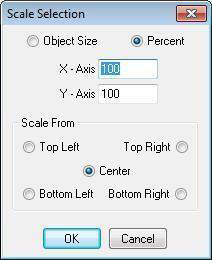
Click the Resize Selected Tool. The Scale Selection dialog box appears. (alternatively) Click Options menu > Scale Selection.
-
Choose either Object Size or Percentage, then enter values to scale the object.
-
In the Scale From section, choose a location to use as the base point during the scaling operation. For instance, clicking Bottom Right means that location will remain constant.
- Click OK.
To skew objects 
-
Click the Selection Tool and then click to select the element.
-
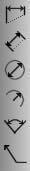
On the Standard Toolbar, click the Skew Tool.
-
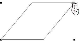
Click a corner point of the element; hold down the mouse button and move the pointer in the direction that you want the element to be slanted. Dimensions appear in the position readout bar, as you draw.
-
Release the mouse to stop skewing the element.
To trim objects
-
Click the Selection Tool and then click to select the element.
-
On the Standard Toolbar, click the Trim Tool.
-
Click the point on the segment where you want to trim (or break) the element into two separate segments.
To join arcs, lines, or polylines 
1- Click the Selection Tool, then hold down SHIFT and click to select each component that you want to be joined.
Note: The end points of each component must be nearby for those components to be joined. You can increase or decrease the necessary distance by changing the Join Sensitivity, see “Controlling Drawing Settings”.
2- On the Standard toolbar, click the Join Tool. The components are joined into a polyline.
Note: You can separate the segments of any polyline (whether or not you created it using the Join Tool) by selecting the polyline and clicking the Unjoin Tool on the Standard toolbar.
To place an element on top of another element 
- Click the Selection Tool and then click to select the element you want to place on top.
- Click the Bring To Front button. (alternatively) Click Arrange menu > Bring To Front.

To place an element behind another element
-
Click the Selection Tool and then click to select the element you want to place on the bottom.
-
Click the Send To Back button. (alternatively) Click Arrange menu > Send To Back.

To clear elements
Right-click the element and choose Clear from the context menu.
Flipping Elements
The Flip function takes the original element and reverses it either horizontally or vertically.
To flip horizontally 
-
Click the Selection Tool and then click to select the element you want to flip.
-
Click the Flip Horizontal button. (alternatively) Click Arrange menu > Flip > Horizontal.
To flip vertically 
-
Click the Selection Tool and then click to select the element you want to flip.
-
Click the Flip Vertical button. (alternatively) Click Arrange menu > Flip > Vertical.
Mirroring Elements
Mirror works similarly to the Flip function. The difference is that mirror leaves the original and makes a duplicate. Mirror creates two identical elements facing one another.
To mirror horizontally 
-
Click the Selection Tool and then click to select the element you want to mirror.
-
Click the Mirror Horizontal button. (alternatively) Click Arrange menu > Mirror > Horizontal.
To mirror vertically 
-
Click the Selection Tool and then click to select the element you want to mirror.
-
Click the Mirror Vertical button. (alternatively) Click Arrange menu > Mirror > Vertical.
Duplicating Elements
Similar to cutting and pasting, the duplicate feature creates an exact copy of the element you select. In the Duplicate Offsets dialog box, you can specify the number and specific offset of a series of duplicates.
To create a duplicate
-
Click the Selection Tool and then click to select the element you want to duplicate.
-
Click Edit menu > Duplicate Object (or press CTRL+D).
To create a series of duplicates
- Click the Selection Tool and then click to select the element you want to duplicate.
2- Click Edit menu > Duplicate Offsets. The Duplicate Offsets dialog box is displayed.
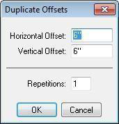
3- Type the horizontal and vertical offsets and the number of duplicates.
Note: These variables control the distance apart that the duplicates are placed.
4- Click OK. The element is duplicated at the offset you defined.

Grouping Elements
By defining a Group, you create a set of selected elements that are then treated as one item. You can have unlimited groups in a drawing.
To control groups
-
Press and hold SHIFT and then click each element that you want to be included in the group.
-
On the Control toolbar, click the Group Tool. The selections are grouped as one element.

Click the Ungroup Tool to ungroup a set of elements. (alternatively) Click Arrange menu > Group or Ungroup.
Locking Elements
You can protect CAD components or symbols from accidental modifications by locking them. You can have unlimited locked elements in a drawing.
To control locks
-
Click to select the element you want to edit. (optional) Hold down SHIFT and click to select multiple elements.
-
On the Control toolbar, click the Lock Tool to lock the selection(s) in place.

- Click the Unlock Tool to unlock the selection(s). (alternatively) Click Arrange menu > Lock or Unlock.

Controlling Drawing Settings
There are a variety of tools that allow you to control how you draw, select, or modify CAD components and symbols. The Preferences dialog box lets you modify a variety of settings, including the number of sides on a multigon or the sensitivity of snap or join tools.
Tools along the bottom of the drawing window allow you to draw parallel segments, switch between object and point selection modes or center and corner drawing modes.
Drawing Preferences
Drawing preferences are default settings that affect all tools and objects as your draw. These settings are controlled in the Preferences dialog box.
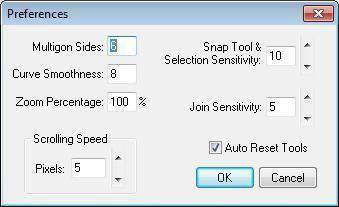
- Multigon Sides controls the number of sides on a selected multigon and changes the number of sides with which multigons are drawn.
- Curve Smoothness defines the default curvature. Lower values result in less curvature.
- Zoom Percentage defines the amount of magnification that is applied each time you click the Zoom Tool.
- Scrolling Speed allows you to increase or decrease the rate at which the drawing window moves when you click the scroll arrows.
- Snap Tool & Selection Sensitivity allows you to increase or decrease the snap radius. A lower value means that you must click closer to an element to snap to or select it.
- Join Sensitivity allows you to Increase or decrease the join radius. A lower value means that you must position elements closer to join them.
- Auto Reset Tools checkbox controls tool behavior. When deselected, you can draw concurrent CAD components without selecting the corresponding CAD tool each time; when selected the tool resets to inactive after you use it.
To change drawing preferences
- Click Options menu > Preferences. The Preferences dialog box is displayed.
- Edit the preferences you want and then click OK.
Drawing Scale
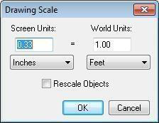
The drawing scale defines how the details on the screen relate to the actual size. When adjusting the drawing scale, you can choose to update existing elements in your design by rescaling them to reflect the new scale.
- Screen Units defines the size of the objects on the screen that correlates to a real-world size. Higher values in the screen units section make it easier to draw small details.
- World Units defines the actual size of objects in the real world that correlates to the screen size. Higher values in the world units section make it easier to draw large details.
- Rescale Objects checkbox updates existing objects to the new scale when selected; when deselected existing objects are unaffected by changes to the scale.
To change the drawing scale
- Click Project menu > Drawing Scale. The Drawing Scale dialog box is displayed.
- Edit the scale units and settings as needed and then click OK.
Paper Size
The drawing area is determined by the paper size setting. Depending on your needs, you can adjust the paper size so your design is created on a realistic page. You can choose one of the four output styles, then select a standard size from the corresponding drop-down menu, or choose to define a custom size.
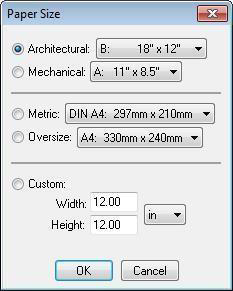
To change the paper size
- Click Project menu > Paper Size. The Paper Size dialog box is displayed.
- Choose an output style and size or choose Custom and define the width, height, and unit of measurement.
- Click OK.
To display the drawing pages
Click Project menu > Draw Page Breaks. When a checkmark is visible page breaks are enabled
Drawing Origin Position
By default, the drawing origin is positioned at 0,0. You can change the position of the origin by selecting a point or by manually defining its position along the horizontal and vertical axis.
To display the drawing axis
Click Project menu > Draw Axis. The axis lines are dotted lines drawn through the origin. When a checkmark is visible the axis is visible.
To set the drawing origin by clicking a point
Right-click in the drawing area where you want the origin and choose Set Origin from the context menu. The origin is repositioned to that point.
To move the drawing origin by defining X and Y
1- Click Project menu > Move Origin. The Move Origin dialog box is displayed.
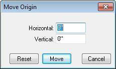
2- Type a new value in the Horizontal and Vertical text boxes and then click Move. The drawing origin is moved by the horizontal and vertical increment you specified.
(optional) Click Reset to reset the origin to 0,0.
To change the axis color

-
Click Project menu > Axis Color. The Color dialog box is displayed.
-
Click an area on the color spectrum window to select a color, then adjust the values, if necessary. (optional) Adjust the current Red, Green, and Blue values to create a custom color.
-
Click OK. The color you defined is applied to the axis.
To change the drawing color
-
Click Project menu > Drawing Color. The Color dialog box is displayed.
-
Click an area on the color spectrum window to select a color, then adjust the values, if necessary. (optional) Adjust the current Red, Green, and Blue values to create a custom color.
-
Click OK. The color you defined is applied to the drawing.
To change the background color
-
Click Project menu > Background Color. The Color dialog box is displayed.
-
Click an area on the color spectrum window to select a color, then adjust the values, if necessary. (optional) Adjust the current Red, Green, and Blue values to create a custom color.
-
Click OK. The color you defined is applied to the drawing background.
Drawing Parallel Segments
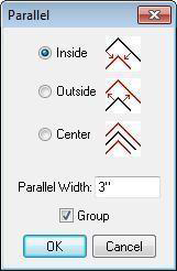
You can draw one or more parallel segments for any CAD component. Use the Parallel dialog box to specify the number of parallel segments, as well as their distance and direction from the original.
- Inside, Outside, and Center specify the direction for the parallel segment.
- Parallel Width defines the distance between the original and parallel segments.
- Group checkbox allows you to automatically group the original and parallel segments. When selected, the segments are grouped; when deselected they are not.
To control the settings for parallel segments
- Click Options menu > Parallel. The Parallel dialog box is displayed.

- Choose a direction to draw the offset parallel and then type a new value in the Parallel Width text box. This controls the distance between the original and parallel segments.
 (optional) Select the Group checkbox to automatically group the original and parallel segments.
 - Click OK.
To enable/disable parallel segments
-
Click Turn On Draw Parallel in the lower left corner of the window. When a single line is visible parallel segments are disabled.
-
Click Turn Off Draw Parallel in the lower left corner of the window. When a double line is visible parallel segments are enabled.
Using Object or Point Selection Modes 
Object Selection Mode is active by default. Object selection, along with point selection, controls how your edits impact your object. If you are in object selection mode, changes affect the object as a whole. If you are working in point selection mode, each edge of the object is treated separately, as you edit.
In point selection mode, you are able to resize or reshape an object by moving one of its individual points. While it is easy to move an entire object in object selection mode, it is much more convenient to handle detailed edits, using point selection mode.
For more information, see “Controlling Selection Mode”.
Drawing from Corner or Center 
You can draw a CAD component from corner to corner or from center to corner. Draw from Corner
makes drawing cabinets, tables, and most other angular components much easier. Draw from Corner works with the rectangle, oval, and line/plane tools only.
For more information, see “Drawing from Corner or Center”.
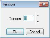
Changing Curve Tension
To further control the look of the shapes drawn with any of the arc or curve tools, you have control over the degree of curve assigned to them. With the Unsmooth feature it is easy to create angular shapes and with Curve Tension you can change the appearance. Curve Tension is measured between 1 and 20. Specifying 1 in the dialog box results in very little tension being applied, while specifying 20 is the maximum amount allowed and causes a greatly- exaggerated curve. For more information, see “Changing Curve Tension”.
To change curve tension 
-
Click to select an element.
-
Click the Smooth/Unsmooth Selected button then click Smooth. The Tension dialog box is displayed.
(alternatively) Click Options menu > Tension.
- Type the amount of tension that you want and then click OK. The Curve Tension you specified is applied.
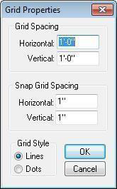
Changing Grid Settings

By default, the grid is visible and set at twelve inches. This way you can visualize that each large square in the Design window is one (1) square foot. By customizing the grid, you can design to fit your specific needs. In addition, by turning the Snap Grid on and off, you will be able to make detailed placement of the detail components simple. For more information, see “Using the Grid”.
To control grid visibility 
Click the Grid On/Off Toggle at the lower left of the window. If Grid Visible is checked, it is displayed. If unchecked, the grid is hidden from view. (alternatively) Click Project menu > Grid > Grid Visible.
To turn off the snap grid 
Click the Snap Grid On/Off Toggle, at the lower left of the window or on the Project menu, click Grid, Snap to Grid. If Snap to Grid is checked Snap to Grid is on. If unchecked, Snap to Grid is off.
To change the grid color
-
Click Project menu > Grid Color. The Color dialog box is displayed.
-
Click an area on the color spectrum window to select a color, then adjust the values, if necessary. (optional) Adjust the current Red, Green and Blue values to create a custom color.
-
Click OK. The color you defined is applied to the drawing grid.
Using Snaps to Draw CAD Components
Punch! Home & Landscape Design Software includes the power of snaps. With snaps, you can define exactly what distance CAD components are placed from other CAD components. You can TAB through the Snaps Toolbar. Each time you press TAB, the next Snap Tool is activated, SHIFT+TAB reverses the process.
Note: Each Snap Tool defaults back to “No Snap” after it is used; double-clicking the Snap Tool will lock it in active mode.
For more information, see “Using Snaps to Draw Components”.
To snap a CAD component to the drawing origin 
-
Click one of the CAD tools.
-
On the Snaps toolbar, click the Snap to Drawing Origin Tool, or press TAB to move through the tools on the Snaps toolbar.
-
Click in the Section Detailer window. The CAD component will “snap to” the drawing origin.
Note: For information on moving the drawing origin, see “Controlling Drawing Settings”.
Viewing your Drawing
The Section Detailer supports the same zoom and pan capabilities you can use when viewing your design in 2D.
For more information, see “Zooming in and Out in 2D”, on page 38 and “Panning Across the 2D Drawing”
Exporting and Importing a DXF/DWG File
You may find it useful to share files with your architect, builder and others involved in your design process. Importing and exporting your detail drawings to DXF or DWG format will make sharing your files simple.
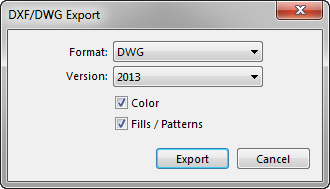
To export a DXF/DWG drawing
-
Click File menu > Export DXF/DWG. The Export Options dialog box is displayed.
-
Choose a format and a version number for your file.
-
You can include Colors, and Fills / Patterns by checking these options.
-
Click OK. The Export DXF/DWG dialog box is displayed.
-
Type a file name in the File Name text box. Punch! Home & Landscape Design Software automatically adds the DXF or DWG extension.
-
Click Save.
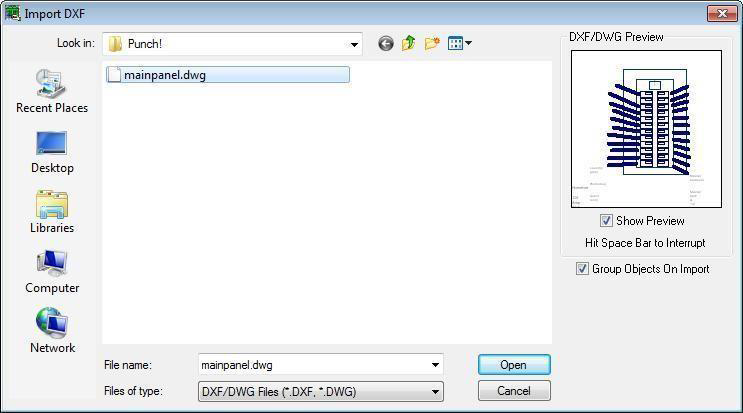
To import a DXF/DWG drawing
-
Click File menu > Import DXF/DWG. The Import DXF dialog box is displayed.
-
Find the file you want to import and then click to select it. (optional) Select the Group Objects on Import checkbox to group all elements in the DXF/DWG together.
-
Click Open.
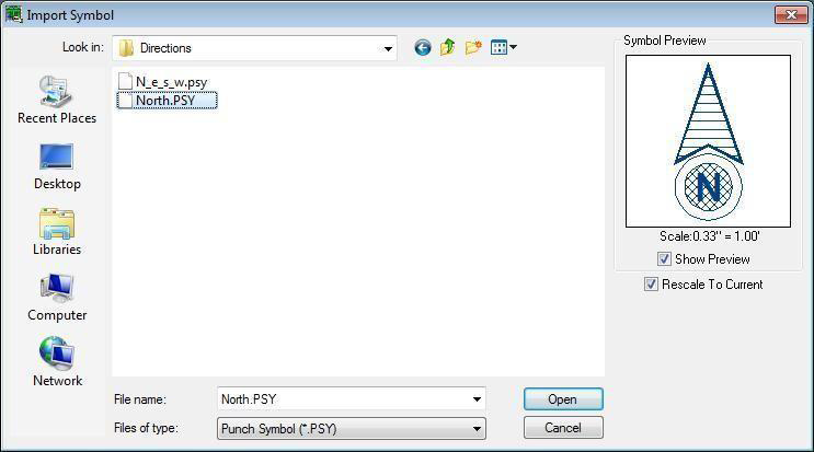
To import a Symbol
-
Click File menu > Import Symbol. The Import Symbol dialog box is displayed.
-
Find the file you want to import and then click to select it. (optional) Select the Rescale to Current checkbox to use the scale currently set.
-
Click Open.