Ceiling Designer
Imagine an exquisite ceiling design with exotic wood beams, opening up an inspirational great room; now create it with Ceiling Designer! Punch! Ceiling Designer offers tools and designs that allow you to capture the ceiling of your dreams and make it real.
Note: It is recommended that you disable the auto ceiling in the main application if it is enabled in your design before opening the Ceiling Designer. For more information, see “Automatic Ceiling”
To Launch Ceiling Designer
-
Click Design menu > Launch PowerTool. The PowerTool Launcher is displayed.
-
Click to select Ceiling Designer and click the Launch button. The Ceiling Designer is launched.
Placing an Auto Ceiling
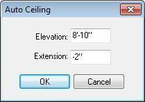
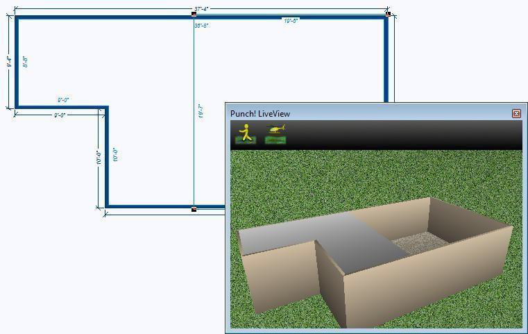
You can automatically place a ceiling over an enclosure with just a couple clicks of the mouse. Once placed, you can edit the ceiling’s shape, size, and properties. The Auto Ceiling dialog box is available when you click an existing wall
in the design. You can set the elevation and the extension before placing the auto ceiling, and then edit it after the ceiling has been placed.
To create an Auto Ceiling
- On the workspace, select an existing wall and click Auto Ceiling. The Auto Ceiling dialog box is displayed.
- Type the Elevation and Extension you want in the corresponding text boxes and then click OK.
Drawing a Custom Ceiling
The first step to creating a creative and unique ceiling is to select the shape you want. Punch! offers ceiling tools to create a ceiling from basic 2D shapes, pre-drawn ceiling templates, and curved shapes. All of these elements are available on the tool menu.
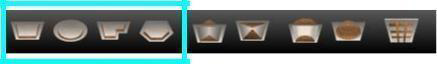
 Rectangle Ceiling Tool
For more information, see “Drawing Rectangles and Squares”.
 Oval Ceiling Tool
For more information, see “Drawing Circles and Ovals”.
 Polygon Ceiling Tool
For more information, see “Drawing Polygons”
 Multigon Ceiling Tool
For more information, see “Drawing Multigons”
Custom Drawn Ceiling Properties
You can edit custom drawn ceilings to adjust the shape as well as create a custom ceiling tray or convert the shape to a ceiling cutout.
Note: Always press ENTER to accept new values in a text box.
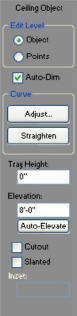
1- Edit Level Select Object to resize the whole object or Points to edit individual points on the shape. For more information, see "Editing Detail Shapes"
2- Auto-Dimension Checkbox controls the displays of dimensions in 2D. When selected, dimensions are displayed.
3- Curve options control curvature. For more information, see "Changing Curve Tension".
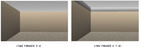
4- Tray Height defines the height of the ceiling tray. When set to 0, the ceiling remains flat. When a feet-and inches value is entered, the tray is created to the specified heights.
5- Elevation defines the elevation at which the ceiling is placed. This does not include the tray height.
6- Auto-Elevate button allows you to automatically detect the wall height and position the ceiling at an elevation relative to the top of the walls.
7- Cutout checkbox specifies a shape as a cutout section, so the area is literally cut out from the existing ceiling.
Note: Be sure the cutout’s elevation matches that of the existing ceiling.
8- Slanted checkbox controls if a slanted angle is applied to the ceiling tray. When selected, the Inset text box becomes active where you can define the distance you want the ceiling to slant towards the top of the tray. A higher Inset value results in a more sloped, more severe pitch.
Drawing a Predefined Ceiling Shape
The predefined ceiling shapes allow you to create ceilings using unique shapes and then adjusting their properties to further customize the look.
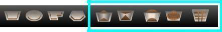

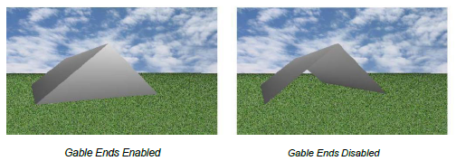
Gable Ceiling Tool
Creates a pitched ceiling with gable ends. Gable ceilings are created using the same drawing method as rectangles and squares. For more information, see “Drawing Rectangles and Squares”. You can edit its properties on the Properties tab before or after you’ve drawn the shape.

Hip Ceiling Tool
Creates a pitched ceiling with slanted panels. Hip ceilings are created using the same drawing method as rectangles and squares. For more information, see “Drawing Rectangles and Squares”. You can edit its properties on the Properties tab before or after you’ve drawn the shape.

Barrel Ceiling Tool
Creates a curved ceiling with two flat ends. Barrel ceilings are created using the same drawing method as rectangles and squares. For more information, see “Drawing Rectangles and Squares”

Dome Ceiling Tool
Creates a rounded ceiling. Dome ceilings are created using the same drawing method as ovals and circles.
Ceiling Beam Tool
Creates an individual beam based on the length you specify. Ceiling beams are created using the same drawing method as line. For more information, see “Drawing Lines”, which begins on page 234. You can edit its properties on the Properties tab before or after you’ve drawn the shape.
Hip and Gable Ceiling Properties
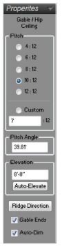
Hip and Gable ceilings are defined by their pitch, elevation, and ridge direction. You can define the pitch before or after drawing the ceiling. This and other properties can be edited by selecting the ceiling in the design window after it has been created.
Note: Always press the ENTER key to accept new values in a text box.
1- Pitch specifies the pitch of the ceiling panels. Choose the radio button corresponding to the pitch you want or choose Custom and type the pitch you want in the text box
2- Pitch Angle defines the ceiling panel pitch angle if you know that. Type the angle you want, in the Pitch Angle text box. The value in the Custom Pitch text box changes to reflect the pitch angle you've entered.
3- Elevation defines the elevation at which the base of the ceiling is placed.
4- Auto-Elevate button allows you to automatically detect the wall height and position the ceiling at an elevation relative to the top of the walls.
5- Ridge Direction button controls the diretion of the ridge, either horizontally or veritcally, depending on its original position.
6- Gable Ends checkbox controls if the ends of the gable ceiling are enabled ordisabled. When enabled, ends are visible, when disabled the ends are removed creating an open-ended gable ceiling.
7- Auto-Dimension checkbox controls the displays of dimensions in 2D. When selected, dimensions are displayed
Barrel and Dome Ceiling Properties
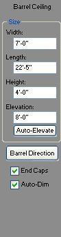
When a barrel or dome ceiling is selected, its properties are displayed on the Properties Bar.
Note: Always press the ENTER key to accept new values in a text box.
- Size defines the Width, Length, and Height of the ceiling (you can also drag an edge to resize manually).
- Elevation defines the elevation at which the base of the ceiling is placed.
- Auto-Elevate button allows you to automatically detect the wall height and position the ceiling at an elevation relative to the top of the walls.
- Barrel Direction button controls the direction of the barrel center line, either horizontally or vertically, depending on its original position.
- Ends Caps checkbox controls if the ends of the barrel ceiling are enabled or disabled. When enabled, ends are visible; when disabled the ends are removed creating an open-ended barrel ceiling.
- Auto-Dimension checkbox controls the displays of dimensions in 2D. When selected, dimensions are displayed.
Ceiling Beam Properties
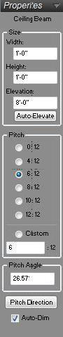
Ceiling beams are defined by their size, elevation, and pitch. You can define the size before or after drawing the beam.
This and other properties can be edited by selecting the beam in the design window after it has been created.
Note: Always press the ENTER key to accept new values in a text box.
- Size Type the Width and Height for the beam in the corresponding text boxes. You can also drag selection points to resize manually.
- Elevation defines the elevation at which the ceiling beam is placed.
- Auto-Elevate button allows you to automatically detect the wall height and position the ceiling beam at an elevation relative to the top of the walls.
- Pitch specifies the pitch of the beam. Choose the radio button corresponding to the pitch you want or choose Custom and type the pitch you want in the text box.
- Pitch Angle defines the ceiling beam pitch angle if you know that. Type the angle you want, in the Pitch Angle text box. The value in the Custom Pitch text box changes to reflect the Pitch Angle you’ve entered.
- Pitch Direction button controls the direction of the beam is pitched. Click to reverse the beam pitch direction.
- Auto-Dimension checkbox controls the displays of dimensions in 2D. When selected, dimensions are displayed.
Editing a Ceiling
Ceiling Designer offers a variety of ways to customize and edit your ceiling. You can control the shape, size, pitch, and other factors that affect the appearance of both a custom ceiling and an Auto Ceiling. Using these tools, you can design unique and creative ceilings. You can only reshape
Ceiling shapes created using the custom ceiling shape tools; predefined ceiling shapes cannot be reshaped. After you’ve created your ceiling, click the ceiling to select it; its properties are displayed on the Properties Bar.
The following options are available for editing your ceiling design:
 Selection Tool (For more information, see “Moving a Selection” and “Reshaping and Resizing 2D Objects”).
 Rotate Tool (For more information, see “Rotating a Selection”.)
 Resize Segment Tool (For more information, see “Changing Segment Length”)
 Add Point Tool (For more information, see “Editing Detail Shapes”)
 Remove Point Tool (For more information, see “Editing Detail Shapes”)
 Fillet Tool (For more information, see “Editing Detail Shapes”)
 Inverse Fillet Tool (For more information, see “Editing Detail Shapes”)
 Chamfer Tool (For more information, see “Editing Detail Shapes”)
Flipping & Mirroring Elements
The Flip function takes the original component and reverses it either horizontally or vertically. Mirror works similarly to the Flip function. The difference is that mirror leaves the original and makes a duplicate. Mirror creates two identical components facing one another.
For more information, see “Flip and Mirror”.
Define Ceiling Elevations
Not only can you control your Working Elevation and individual component elevations, but Ceiling Designer is also equipped with an Auto-Elevate feature, which automatically elevates new ceilings and adjusts existing ceilings, according to elevation changes.
- Auto-Elevate new ceilings When selected, new ceilings are automatically added at a default ceiling elevation.
- Adjust ceilings on elevation changes When selected existing ceilings are automatically updated when changes are made that affect the ceiling height.
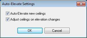
To control auto-elevate settings
- Click Design menu > Auto-Elevate Settings. The Auto-Elevate Settings dialog box is displayed.
- Edit the settings and then click OK.
Controlling Your 2D View
While creating your ceiling design, you’ll use a variety of tools and views, so it will be helpful to be able to adjust your 2D view, quickly, to accommodate your needs. You can pan, or move, across your entire design using the Pan Tool, zoom in and out to focus on specific areas, as well as quickly fit your entire design within the 2D window.
For more information, see “Viewing the 2D Plan”.
2D Drawing Colors
To help distinguish the ceiling you’re working on from the rest of your design, and possibly the grid, you can customize the color of your 2D ceiling while working in Ceiling Designer.
To change your drawing color
- Click 2D menu > Drawing Color. The color palette is displayed.
- Choose the color you want your ceiling components to be and click OK.
To reset drawing colors
- Click 2D menu > Reset Drawing Color.
3D View Window Options

3D View offers three different 3D views for you to see your design as you’re creating. The 3D View window can be repositioned and resized at any time during the design process. The 3D View window sizes are accessible through buttons in Ceiling Designer, and by right-clicking on the 2D workspace.
For more information, see “Working with 3D Views”.
Navigating in 3D

You can navigate through your 3D view using a Walk-Through and Fly-Around feature. As you’re navigating, you can adjust your viewing elevation, and even anchor your position using the Controlled navigation tools.
As you navigate through your design, you can adjust the speed at which you’re moving and adjust the size of the camera angle.
For more information, see “Moving Around in 3D”.
3D Rendering Options
Rendering options are available to control 3D navigation and viewing settings.
- Speed slider controls the navigation speed, from slow to fast.
- Camera Angle slider control how thin or wide the 3D view is displayed.
- ClearView Opacity slider controls how transparent or opaque components appear when in ClearView.
- Render 3D components that have been added to your drawing are automatically displayed when viewing your drawing in Ceiling Designer. You can select which 3D components are displayed or hide all to help speed up rendering. Click to select, or deselect the options to include, or exclude.
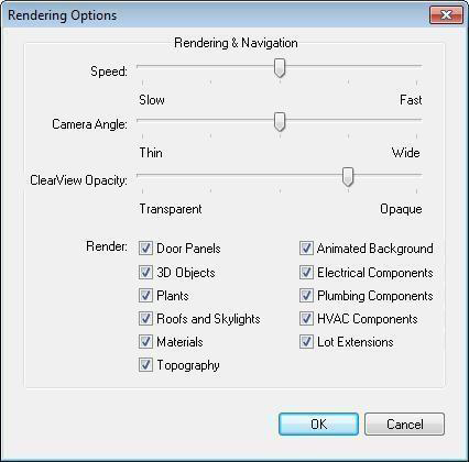
Note: The faster the viewing speed, the lower the quality of the rendered 3D image.
To access rendering settings
- Open a 3D View window.
- Click 3D menu > Rendering Options. The Rendering Options dialog box is displayed.
- Adjust the render settings and then click OK.
Selecting Render Style
There are two rendering styles to choose from when viewing your design in 3D. Each offers a different perspective of your drawing.
To view in 3D textured
-
Open 3D View.
-
On the 3D menu, click to deselect ClearView. The design is displayed in 3D texture in the 3D View window.
To view in ClearView
-
Open 3D View.
-
On the 3D menu, click ClearView. The design is displayed in ClearView in the 3D View window.
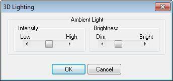
Adjusting 3D Lighting
You can control the intensity and brightness of lighting of your 3D view in Ceiling Designer.
To adjust lighting intensity in a 3D view
-
Click 3D menu > 3D Lighting. The 3D Lighting dialog box is displayed.
-
Adjust the sliders to control Intensity and Brightness and then click OK.
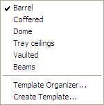
Using Templates
Punch! Ceiling Designer offers pre-made ceiling designs to quickly place in your drawing. You can also create and manage your own templates, which is extremely useful when working with multiple ceilings throughout multiple designs. The Template Organizer allows you to manage all of your templates; you can move them between categories, rename templates and categories, as well as delete templates and categories.
To use templates
-
Click the Templates tab. The ceiling templates are displayed.
-
Click the Templates drop-down menu and choose the ceiling library you want. The templates are displayed on the Properties Bar.
-
Drag-and-drop a template onto the workspace.
Note: The position of your cursor, when you drag and drop a template, determines the center of the design.
To organize templates
-
From the Templates drop-down menu, click Template Organizer.
-
On the left side of the Organizer, select a category from the drop-down menu.
-
On the right side of the organizer, select a category from the drop-down menu.
-
Click on the name of the template you want to move.
-
Click the navigation arrows to move templates from one category to another.
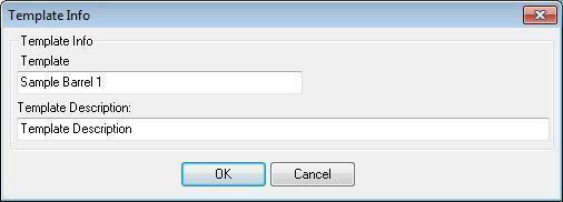
To change template info 
- Select the ceiling template you want to change and click the Info button, under Template. The Template Info dialog box is displayed.
- Type the name you want, in the Template text box.
- Type a description in the Template Description text box.
- Click OK.
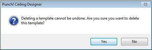
To delete a template
- Click the template you want to delete to select it.
- Click the Delete button, under Template. A confirmation box is displayed.
- Click Yes to permanently delete the template from the library.
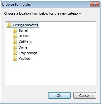
To create a new ceiling category
- Click the New button under Category. The Browse for Folder dialog box is displayed.
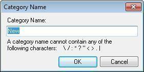
- Select a folder for the location of your new category and click OK. The Category Name dialog box is displayed.
- Type the name of your new category in the Category Name text box and click OK. Your new category is displayed on the right side of the Organizer.

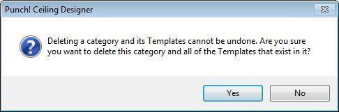
To delete a category
- Click the Delete button under Category. The Browse for Folder dialog box is displayed.
- Select the category you want to delete and click OK. The delete confirmation box is displayed.
- Click Yes to permanently delete the category and its templates from the Organizer.

To rename a category
- Click the Rename button under category. The Browse for Folder dialog box is displayed.
- Select the category you want to rename and click OK. The Category Name dialog box is displayed.
- Type the new name in the Category Name text box and click OK. The new category name is displayed in the Organizer.

To create a ceiling template
- Create a ceiling design you want to save as a template and then click to select the ceiling element(s) you want to include in your template.
- Click the Templates Tab. Templates are displayed on the Properties Bar.
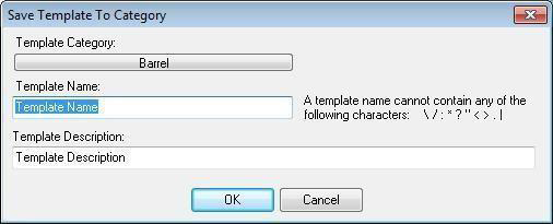
- Click the Templates drop-down menu and choose Create Template. The Save Template to Category dialog box is displayed.
- Click the Template Category drop-down menu to select the category where you want to save your ceiling template.
- Type the name of your ceiling in the Template Name text box.
- Type a description of your ceiling in the Template Description text box.
- Once you’ve finished entering the information about your new ceiling, click OK. Your design is displayed on the Templates Properties Bar.
Tip: Use the Templates drop-down menu to navigate through your categories quickly.