Preferences
The Preferences dialog, accessed from the Custom Workshop Pro menu, allows you to customize various start-up and runtime settings for Custom Workshop Pro. The Category section lists the available preference groups. The Settings section displays the interface for the selected category. The preference group settings are detailed below:
Colors
The colors category assigns the foreground and background color.
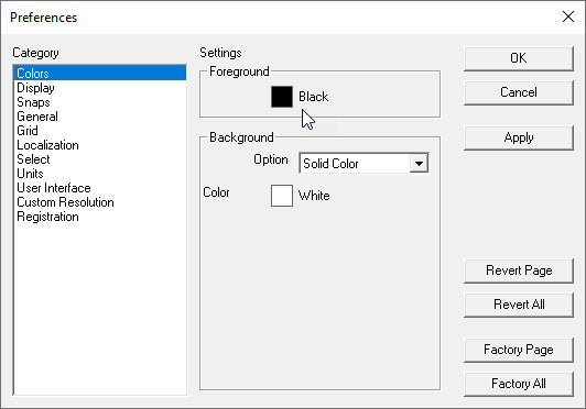
Background Color
Specify the background color of the drawing window.
Foreground Color
Specify the foreground color of the drawing window.
Preview Color
Displays the foreground and background into a preview area.
Display
The Display preferences page sets settings for default display resolutions of curves, surfaces, and solids.
Object Type
The Object Type pull down provides a means to set separate resolution settings for curves, surfaces, and solids.
Resolution
The Resolution pull down menu provides options for setting the resolution between coarse and sup
Pen Weights
The Pen Weights pull down menu provides options for the displayed pen weights that have been customized in the drawing, as they appear when printed.
Printed Line Cap
The Printed Line Cap provides three options that control how line ends are printed. The three options are butt, round, and square. Note, these options are only activated upon printing.
ButtRoundSquare
Snaps
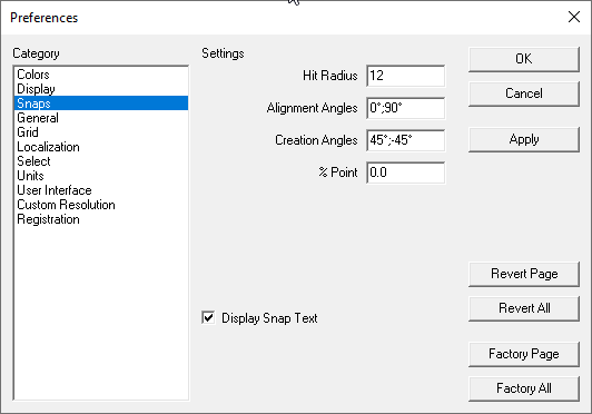
Hit Radius
The pixel radius which is examined for the Snap tool.
Alignment Angles
The angles that are highlighted when referenced from a wake-up snap.
Creation Angles
The angles that are highlighted relative to the first snap point.
% Point
Percentage along a curve that is examined for snap locations.
General
This category assigns general settings including axis, tool tips, short cuts, and dialog positions.
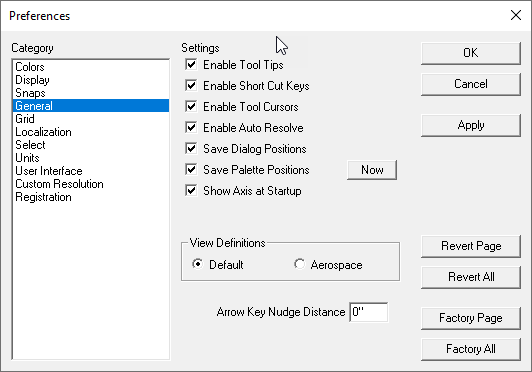
Enable Tool Tips
Displays, in the prompt window, a brief description of an icon as you move your cursor over its tool image.
Enable Short Cut Keys
Turns on or off the ability to use short cuts for quick command access.
Enable Tool Cursors
Turns on or off the ability to use tool cursors. Two types of tool cursors exist which support snapping or selection operations.
Enable Auto Resolve
Immediately resolves dependent geometry when changes are made.
Save Palette Positions
Saves all displayed tool palette positions on the screen when you exit the program.
Show Axis at Start Up
Displays the XYZ axis located at the origin.
View Definitions
Changes the definitions of side and front views to reflect mechanical or aerospace design conventions.
Arrow Key Nudge Distance
The distance used to move objects while in the Select tool using the arrow keys.
Grid
This category assigns the default display grid settings.
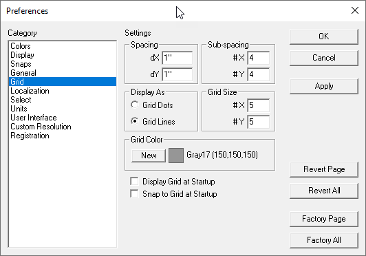
Spacing
The dX and dY spacing between major grid lines.
Sub-spacing
The X Divs and Y Divs (minor grid lines) displayed between the major grid lines.
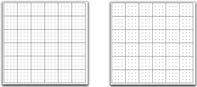
Display As
Displays the grid as dots or lines.
Grid Size
The number of cells in the grid.
Grid Color
The display color for the major grid lines. The minor grid lines are displayed as a different shade of this color.
Display Grid at Startup
Enable this item to display the grid when the program is launched.
Snap to Grid at Startup
Enable this item to activate grid snapping when the program is launched.
Localization
The Localization category displays options specific to language localization.
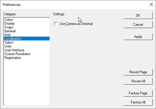
Use Comma as Decimal
Replaces the period used in floating point representations with a comma.
Select
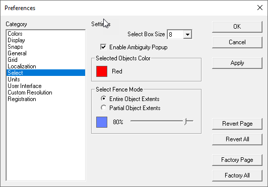
The Select category displays options for picking objects.
Pick Box Size
The pick aperture size for the snap tool and selections.
Enable Ambiguity Popup
Displays a popup menu with all the objects in the pick region. The user then picks the object of interest. If off, the object closest to the view is selected. If the objects are at the same depth, the object that was first created will get selected.
Selected objects Color
Sets color used to indicate a selected object.
Select Fence Mode
Sets the method used for picking with a bounding box. Entire object extents require the user select the complete extents of the object, whereas partial extents require only a portion be fenced to select.
Transparency
The selection box uses window overlays with transparencies. You can control the selection background color and transparency level with the transparency slider located at the bottom of the Select Fence Mode.
The user can modify the color and transparency level associated with the selection box. To change these attributes, display the Preferences dialog box and pick the Select category. The selection transparency and color are controlled under the Select Fence Mode control grouping.
Units
The Units category displays the options for units of measure used for display of numeric values
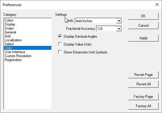
Units
The Units pull down sets the unit format for numbers displayed in dialog boxes and Data Entry Windows. At this time, Custom Workshop Pro supports six different units of measure. These units and their associated symbols are listed below:
| Unit | Symbol | Abbreviations | Example | |
|---|---|---|---|---|
| inches | " | in. | 12.0" | |
| feet | ' | ft. | 1.0' | |
| feet/inches | ' " | ft-in | 1' 0" | |
| millimeter | n/a | mm | 1000 mm | |
| centimeter | n/a | cm | 1000 cm | |
| meters | n/a | m | 1 m |
Display Decimal Digits
Sets the number of digits used to display floating point values in the Data Entry Fields and dialog boxes.
Display Decimal Angles
When checked, this option will display angles as decimal values instead of degrees, minutes, and seconds.
Display Value Units
Use the settings under the Units category to configure the application for working with feet-inches. The data entry window and unit display fields will reflect the current unit settings. When the unit settings are selected as feet-inches, the accuracy menu provides a drop-down list of fractional settings.
The Tool Bar data entry window reflects the preferences for unit settings. When using the feet/inches unit settings, data entry fields will display and process with feet/inches notation.
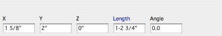
Feet/Inches Settings in Data Entry Window
All fields including the data entry window and dialog input fields support an intelligent unit parser. At any time, you can type in a value supporting any unit expression. Examples include:
-
14' 11"
-
179"
-
3cm
-
4mm
-
14" + 63cm
Be careful about typing in a minus sign between the feet and inches. This will be interpreted as a subtraction expression.
14'-11" = 157inches
Show Dimension Unit Symbols
When checked, this option displays unit of measure symbols for dimensions in the drawing. When unchecked, unit symbols are not displayed. You can also show/hide unit symbols for individual dimensions by selecting the dimension and enabling the unit symbol using the Inspector.
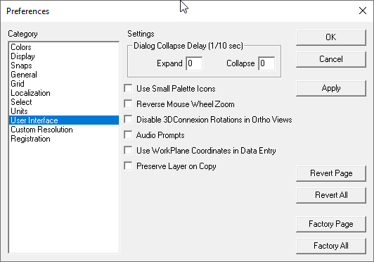
User Interface
The User Interface category displays options for controlling dialogs, icon display, and wheel scroll direction.
Dialog Collapse Timing
The Expand and Collapse time sets a delay for how long the cursor must be out or in a dialog to collapse.
Toolbar Layout
Click the Use Small Palette Icons check box to display icons 24 by 21 pixels. The default icons are 30 by 28 pixels.
Wheel Scroll Direction
For those users with a wheel button on their mouse, there is a new option to reverse the direction of the zoom.
Disable 3DConnexion Rotations in Ortho Views
Select to disable 3DConnexion rotations while in Ortho views.
Audio Prompts
The Audio Prompts check button enables speaking of the message line prompts. This is particularly useful with tasks such as 3D digitizing where reading prompts is difficult.
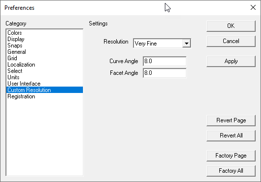
Custom Resolution
The Resolution category allows the user to define custom settings for display resolutions.
- Factory Changes all the settings for all preference groups back to the original installation values.
- Revert All Resets all values to the values prior to opening the dialog box.
- Cancel Resets all values and exits dialog box.
- OK Exits and writes out all changes to the preferences file.