Dimension
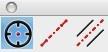
There are eleven tools for creating dimensions. From left to right, these tools are:
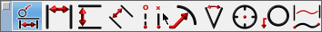
- Smart Dimension
- Horizontal
- Vertical
- Parallel
- Ordinate
- Radial and Diametrical
- Angular
- Center Mark
- Balloon & Callout
- Length Along Curve
The Smart Dimension tool creates an associative link between the dimension and any referenced curve. This means that modifying the curve will automatically update the smart dimension. The other dimension tools do not preserve a relationship between geometry and the dimension.
Dimension Text
You can specify the dimension text or use the # symbol to automatically fill the field based on the measured value. The text is controlled on the Prompt window.
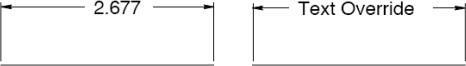
Dimension properties, such as format, orientation, and more, are controlled on the Inspector.

Smart Dimension
The Smart Dimension tool creates horizontal, vertical, parallel, radial or diameter dimensions based the object type selected and where you move your mouse. Dimensions created with this tool are associative to the curves referenced. Modifying the shape of the curve will automatically update the dimension.
Using the Smart Dimension tool (Example 1--HVP Dimension)
- Position the cursor over a line such that the Snap tool says “on”. Click the mouse.
- Move the cursor to place a horizontal, vertical or parallel dimension.
- Click at desired location to accept the final dimension.
Using the Smart Dimension tool (Example 2--Diameter Dimension)
- Position the cursor over a circle such that the Snap tool says “on”. Click the mouse.
- Move the cursor to place a diameter dimension.
- Click at desired location to accept the final dimension.
Using the Smart Dimension tool (Example 3--Point/Point Dimension)
- Position the cursor over an object such that the Snap tool says “endpoint”, “midpoint”, “vertex” or “center”. Click the mouse to specify the dimension start point.
- Position the cursor over an object such that the Snap tool says “endpoint”, “midpoint”, “vertex” or “center”. Click the mouse to specify the dimension endpoint.
- Move the cursor to place a horizontal, vertical or parallel dimension.
- Click at desired location to create dimension.
Using the Smart Dimension tool (Example 4--Angular Dimension)
- Position the cursor over a line such that the Snap tool says “on”. Hold the Shift key and click the mouse.
- While still holding the Shift key, position the cursor over a second line such that the Snap tool says “on”. Click the mouse.
- Release the Shift key.
- Move and click at desired location to accept the angular dimension.
Using the Smart Dimension tool (Example 5--Minimum Distance Curve/Curve)
- Hold the Shift key, and position the cursor over an object such that the Snap tool says “on”. Click the mouse.
- Position the cursor over a second object such that the Snap tool says “on”. Click the mouse.
- Move and click at desired location to accept the minimum distance dimension.
- This creates a minimum distance between two curves.
Using the Smart Dimension tool (Example 6--Minimum Distance Curve/Pt)
- Hold the Shift key, and position the cursor over an object such that the Snap tool says “on”. Click the mouse.
- Position the cursor over a second object such that the Snap tool says “endpoint”, “midpoint” or
“center”. Click the mouse.
-
Move and click at desired location to accept the minimum distance dimension.
-
This creates a minimum distance dimension between a curve and a point on another curve.
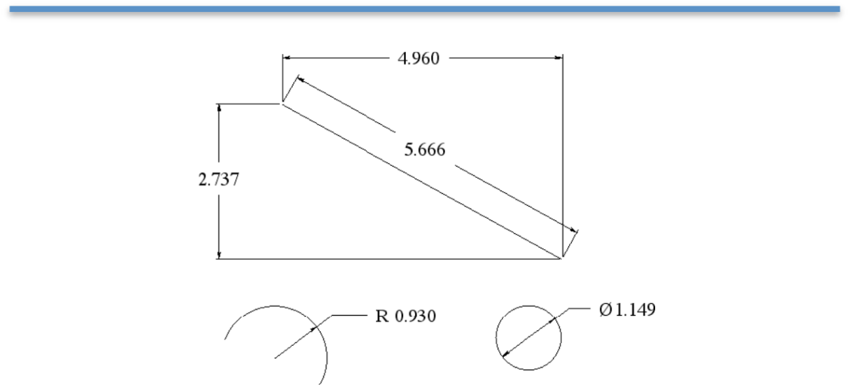
Horizontal Dimensions
A Horizontal Dimension creates a dimension with horizontal leader lines and vertical extension lines. Horizontal and vertical for the drawing are defined by the x and y axis of the construction plane. To create a horizontal dimension, select the object you desire to dimension and locate the position corresponding to the lower right text location. Modifying the object will automatically regenerate the dimension.
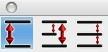
There are three types of horizontal dimensions available, from the sub-tool palette:

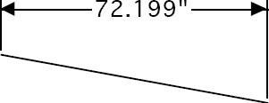
Horizontal Dimension tool
This tool creates a single horizontal dimension, from a specified start point to a specified endpoint. Using the Horizontal Dimension tool
-
Click the mouse for the dimension start.
-
Click the mouse for the dimension end.

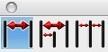
Horizontal Baseline tool
This tool creates a horizontal series of dimensions with one baseline dimension of the entire distance. Using the Horizontal Baseline tool
-
Click the mouse for the dimension start.
-
Click to set a series of horizontal dimensions.
-
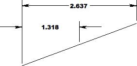
Click the mouse for the dimension end.

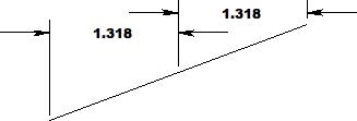
Horizontal Chain tool
This tool creates a horizontal series of individual dimensions over a specified distance. Using the Horizontal Chain tool
-
Click the mouse for the dimension start.
-
Click the mouse for the dimension end.
-
Continue to define individual dimensions along a surface.
Vertical Dimensions
A Vertical Dimension creates a dimension with vertical leader lines and horizontal extension lines.
Horizontal and vertical for the drawing are defined by the x and y axis of the construction plane.
There are three types of vertical dimensions available, from the sub-tool palette:

Vertical Dimension tool
This tool creates a single vertical dimension, from a specified start point to a specified endpoint. Using the Vertical Dimension tool
- Click the mouse for the dimension start.
- Click the mouse for the dimension end.


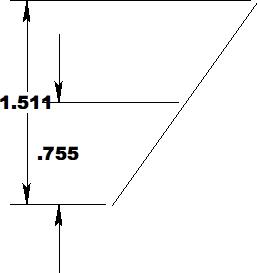
Vertical Baseline tool
This tool creates a vertical series of dimensions with one baseline dimension of the entire distance. Using the Vertical Baseline tool
- Click the mouse for the dimension start.
- Click to set a series of vertical dimensions.
Click the mouse for the dimension end.

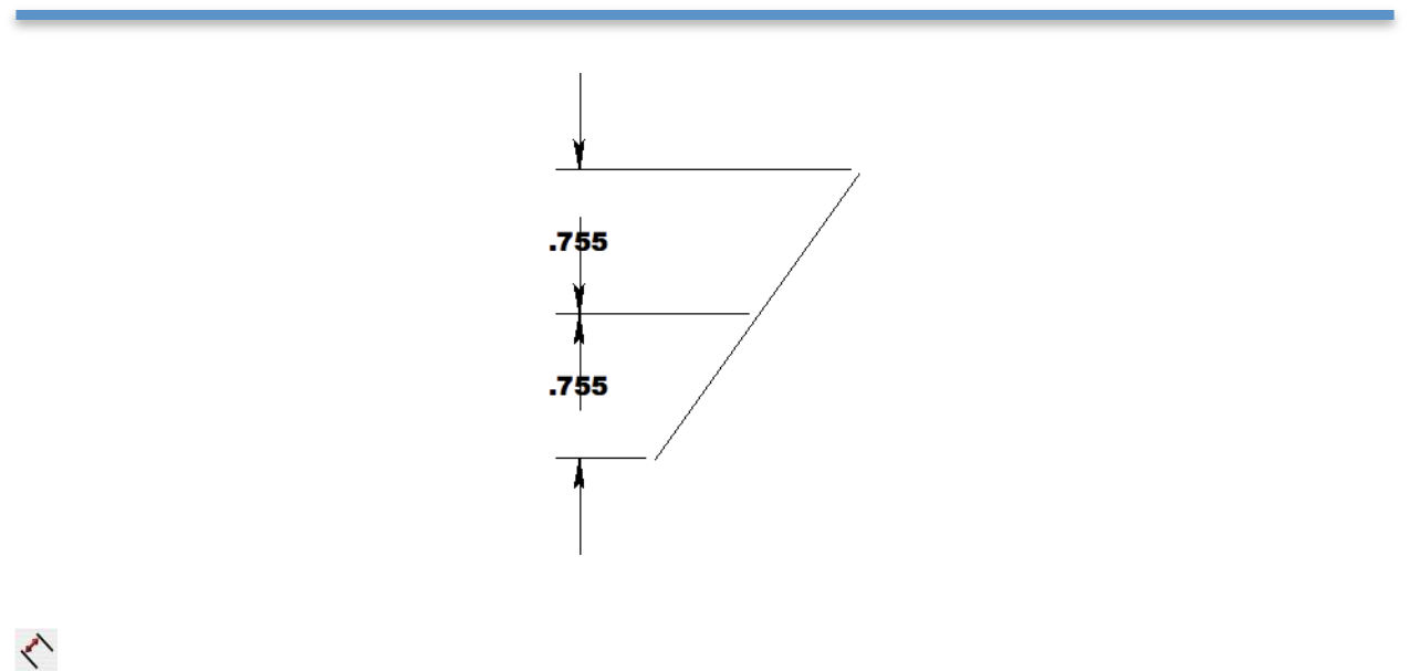
Vertical Chain tool
This tool creates a vertical series of individual dimensions over a specified distance.
Using the Vertical Chain tool
- Click the mouse for the dimension start.
- Click the mouse for the dimension end.
Continue to define individual dimensions along a surface.
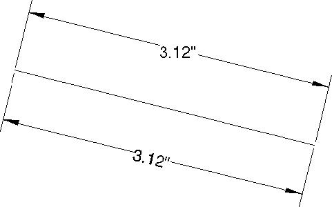
Parallel Dimension
A Parallel Dimension creates a dimension with parallel leader lines and perpendicular extension lines relative to the object selected.
Using the Parallel Dimension tool
- Click the mouse for the dimension start.
- Click the mouse for the dimension end.
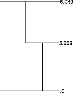
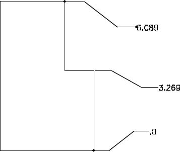
Ordinate Dimensions
The Ordinate Dimension tool dimensions distances relative to a base point. Two options are provided for creating horizontal and vertical ordinate dimensions.

Using the Horizontal Ordinate Dimension tool
-
Click the mouse for the ordinate base point.
-
Click the mouse for additional ordinate dimensions.
-

Select a new tool to stop creating ordinate dimensions

Using the Vertical Ordinate Dimension tool
- Click the mouse for the ordinate base point.
- Click the mouse for additional ordinate dimensions.
- Select a new tool to stop creating ordinate dimensions.
Modifying Ordinate Dimensions
- Select the Arrow tool to modify an ordinate dimension.
- Box select the ordinate dimension near the text location.
- Drag the text label (creating an elbow) to the new location.
-
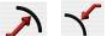
Radial Dimensions
A Radial Dimension measures the radius of a circle or arc and creates a dimension with either arrows inside or arrows outside. The resulting dimension is associative to the arc or circle.
Using the Radial Dimension tool
-
Select an arc or circle.
-
Click the mouse for the dimension end.
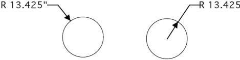
Arrow OutsideArrow Inside

Diametrical Dimensions
A Diametrical Dimension measures the diameter of a circle. To create a diametrical dimension, select a circle and indicate the location of the text. A diametrical dimension is linked to the original object such that any modifications to the object will automatically regenerate the dimension.
Using the Diameter Dimension tool
-
Select an arc or circle.
-
Click the mouse for the dimension end.
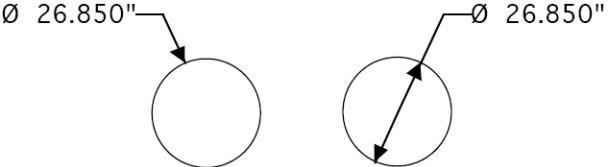
Arrow OutsideArrow Inside

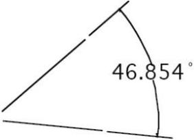
Angular Dimensions
Angular Dimensions measure the angle between any two lines.
Using the Angular Dimension tool
-
Select first line.
-
Select second line.
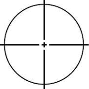
Center Mark Dimension
The Center Mark Dimension will locate and mark the center of a circle or entity. There are three tools available for finding a CenterPoint.

Center Mark Circle
To create a center mark simply select the desired circle. Note that if you change the circle by modifying the radius or moving its position the center mark will automatically regenerate because of the associativity that is created.
Using the Center Mark Dimension tool
- Select circle.

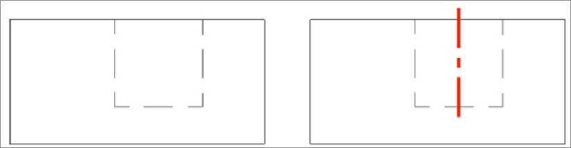
Centerline
The Centerline tool determines the center between two user-defined points. The Axis overlap text field, on the Prompt window, controls how far the line extends beyond each point.
Using the Centerline tool
-
Click to set the first point along which the centerline will follow.
-
Click the next point to draw the line.
-

Centerline Bisector
The Centerline Bisector tool references two lines. The bisector of the of the two lines defines the center line dimension.
The image part with re lationship ID r Id474 wa s not f ound in the file .
Using the Centerline Bisector tool
- Click two lines (or circles) between which you want a centerline drawn.

Balloon and Callout Dimensions
A Balloon Dimension creates a label with a surrounding graphic that may be a circle, square or triangle. A callout dimension contains no surrounding graphics. There are eight balloon dimensions and one callout dimension.

Using the Balloon Dimension tool
- Select balloon type.
- Click location for balloon arrow to point at.
- Click location for text extension line to start at.
- Use the Data Entry Fields to modify the text or width of the enclosing graphic.
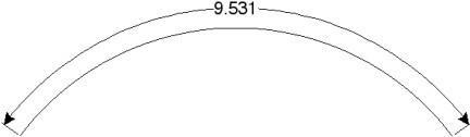
Length Dimension

The Length Dimension creates an associative dimension to the length of a curve.
Using the Length Dimension tool
- Click dimension start location.
- Click dimension end location.