Wireframe Modeling Overview
A wireframe model of an object is the simplest mathematical representation of a part. The word “wireframe” is related to the fact that one may imagine a wire that is bent to follow the object edges to generate a model. Wireframes in TurboCAD consist of points, lines, arcs, circles, ellipses, and conics. These particular wireframes are also collectively referred to as curves and may also be thought of as 2D entities. Although wireframes are very limited in the amount of model content they represent, they are very powerful building blocks for creating more complex, three- dimensional models composed of surfaces and solids.
Wireframe Tools
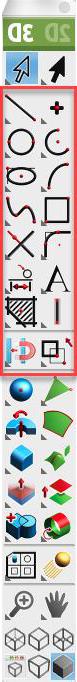
Tools associated with wireframe modeling methods are located in the upper portion of the main tool palette.
Snap Tool and Wireframes
The Snap tool recognizes several useful snap locations associated with wireframe objects. These dynamic snap locations include:
- Endpoints
- Midpoints
- Intersections
- Projections
Selection and Display
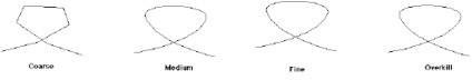
Wireframes are selected by picking a location along the length of the wire. Wires are selected when any portion of the wire passes through the rubber banding select box or single pick box. Conics, ellipses, splines, and circles have resolution attributes that impact the screen display and printer output. Use the Edit: Change Resolution command from the Menu Bar to change a wireframe display resolution.