3D Digitizer
3D digitizing is a fast and flexible way to capture 3D measurements from a physical model. 3D scanning or 3D digitizing, involves creating a digital version of a physical object. Scanning allows a copy of a physical object to be represented electronically; then the electronic version can be manipulated in way the physical version cannot. An electronic model can be kept on a computer’s hard drive, emailed, animated for use in simulation or used as a template for making physical reproductions.
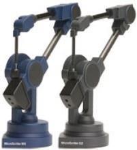
MicroScribe
TurboCAD processes raw 3D data from a MicroScribe device and Baces3D. MicroScribe uses a series of user-controlled snap inference filters. As you trace over your object, feedback is dynamically displayed to the user for endpoints, midpoints, centers, tangents, and alignments. The 3D snap inferencing ensures geometry created with the MicroScribe system is precisely aligned relative to neighboring geometry.
Baces3D
Baces3D is a portable measurement arm that acquires 3-dimensional measures, points, and surfaces within its work-space with a simple manual movement of the user. To use a Baces3D digitizer with Shark, simply plug the device into the USB port. This device is currently only supported on Windows Vista and XP.
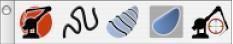
3D Digitizer Tool Palette
3D digitizing offers a collection of specific tools.
3D Digitizer Connect
Use the 3D Digitizer Connect tool to initialize a new session with the digitizing device. Additionally, you will need to use this tool if the MicroScribe or tangent moves. This command creates a coordinate transformation between the target and Shark drawing coordinate system.
Using the 3D Digitizer Connect tool
- Select the 3D Digitizer Connect tool from the tool palette.
- Digitize a location representing the target origin.
- Digitize a location representing a point along the target y axis.
- Digitize two points representing the target extents. These two points should be the extent diagonals of the target.
Digitize Curves
The Digitize Curves tool provides a means to create points, lines, and splines from a continuous stream of digitized data. Additionally, this tool automatically turns off snap inferencing and alignments. If you need snap inferencing, use the Curve Creation tools on the Main Tool Palette. There is a drop-down on the Prompt Window that allows you to specify points, lines, splines, and closed splines. For each of these curve types, you can specify a point sampling value through the Data Entry window, labeled Point Spacing.
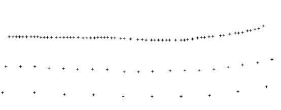
Point Spacing Examples
The spline option provides an additional option for fit tolerance. This is a tolerance used to fit a smooth spline curve to a collection of points. It is useful for removing noise from the sampled data. In the image below, the dark dots represent digitized data points with the curve passing through those points at a specific fit tolerance.
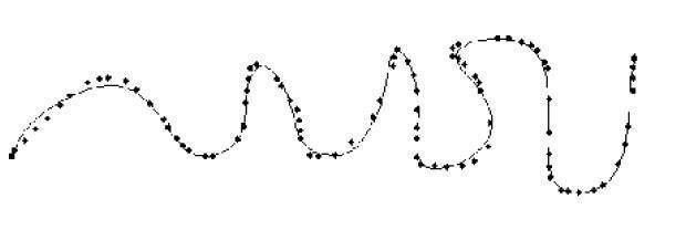
Spline Fit Tolerance
Using the Digitized Curve tool
- Select the Digitized Curve tool from the tool palette. Select the curve type, either point, line or spline.
- Specify the desired point spacing.
- If creating a spline, specify the spline fit tolerance.
- Press and hold the digitizer button. Move the pen and release when done.
Section Surface
The Section Surface tool creates a surface as you digitize from curves spaced along sections. Options for this tool include creation of a mesh (3D facets) or NURBS (Non Uniform B-Spline Surface). Additionally, you can specify the sections by continuously reading the digitizer or single click for each point on the curve.
Using the Section Surface tool
- Select the Section Surface tool from the tool palette.
- Select the surface type, either Mesh or NURBS.
- Select the input, either Continuous or Single.
- Specify the desired point spacing.
- Digitize the first section of the surface. Release your mouse button to end.
- Continue until all the sections for the target are entered.
Sections should not overlap and need to start from the same side of the target, throughout the Section Surface tool, to prevent twisting.
Contour Surface
The Contour Surface tool accepts scanned data in any order and reconstructs a surface from the data. Internally, it reconstructs sections from the scanned data by planar slicing and finally creating a surface from the sections. Slicing planes are controlled by the extent and orientation of the centerline and plane spacing. In the image below, the two spheres represent the start and end centerline. The red curve represents the outer contour to which everything is trimmed. The black curves are the raw MicroScribe scans used for section slicing. These scans can have any orientation, including overlapping. However, you must provide enough scans to fully cover the target area.
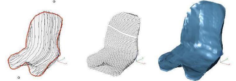
User-Supplied DataSection ConstructionSurface Reconstruction
Contour Surface
Using the Contour Surface tool
- Select the Contour Surface tool from the tool palette.
- Select the surface type, either Mesh or NURB.
- Specify the desired point spacing.
- Digitize two points for the center line. (These two points define the extent and orientation of the slicing planes).
- Digitize the outer contour of the target. Press and hold the button around the entire outer contour.
- Digitize inner contours.
- Select new tool to terminate.
Align
The Align tool is used to reposition the digitized image. This is useful for digitizing models larger than the reach of the arm. Realigning is a two-step process. First, you must mark the model in the current position with three marking points. Second, move the arm, reconnect, and then reference the three previous marking points.
Using the Align tool
- Select the Align tool from the tool palette.
- Select the Set Marking Points option.
- Specify three points on the target as references.
- Move the digitizer to a new position.
- Use the first tool to reconnect to the MicroScribe.
- Select the Align tool from the tool palette.
- Select Align Coordinates from the drop-•down.
- Select the three marking points in the order that they are labeled/created.
- Digitize three points on top of the marking points.
Variables/Equations
The Variables and Equations dialog allows you to create variables which may be constant or mathematical expressions. To access the dialog, to go Window: Variables/Equations.
As you create and assign dimension constraints to geometry, the equation dialog automatically updates with new entries. The Name field contains a unique identifier from the object. The Value field represents its current evaluation expression. The Equation field contains a string expression defining a mathematical relationship. The following types of variables within equations are supported:
- A variable associated with a dimension.
- A simple variable not associated with a dimension.
- Linear equations of the form a1v1+a2v2+a3*v3+...+c = 0.
- Non-linear equations of the form f (v1, v2, v3) = 0.