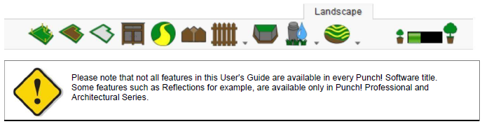
Landscape Plan Tab
From adding a flower bed near your front door to designing an elaborate pool area, Punch! Home Design Software contains an extensive toolset to help you design your outdoor living areas.
You will learn to add a pond, pathways, and fencing to your home plan. In addition, you can create flower beds that you can landscape, using flowers, shrubs, and trees, accessible from the Plant library.
Note: For information on adding plants to your design, see “Plants Libraries”
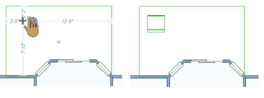
Defining the Property Line
If you are working in a confined or unusually-shaped area, you may want to define the property lines. The property line only appears in the 2D design window.
If you know the exact coordinates you can enter them using the Survey Coordinates window and define your property line based on the data you input (you can also edit a manually drawn property line and adjust the points based on coordinates). There are three coordinate modes available when adding a property line based on coordinates.
Below are some references that may be helpful as you design:
■ Reshaping and Resizing 2D Objects
■ AutoSnap and Alignment Options
■ Elevating Objects
■ Moving a Selection & Nudging a Selection
■ Changing Curve Tension
■Dimensioning
To add a property line manually 
- On the Landscape plan toolbar, click Property Line Tool.
- On the Properties tab, click the Draw Method drop-down menu and choose the shape you want.
- Use the Define 2D Shape drawing method to draw a property line.
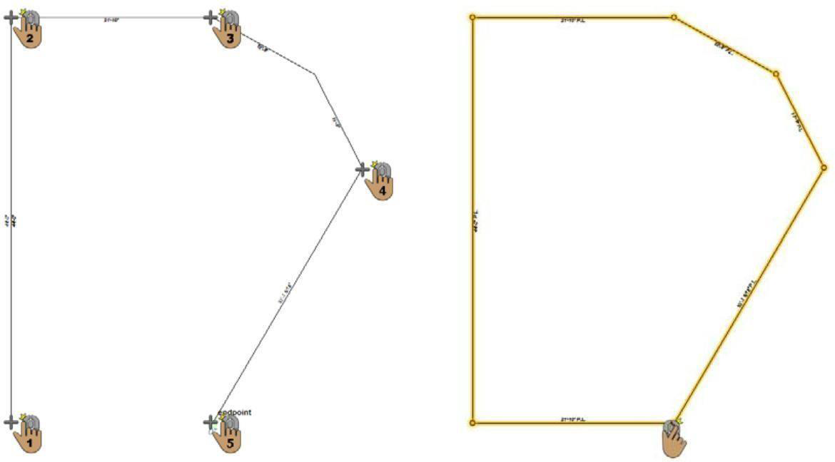
This example shows a railing drawn using the Closed Polygon shape
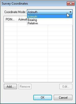
To add a property line by specifying coordinates
-
On the Landscape plan toolbar, double-click Property Line Tool.
-
Choose the Coordinate Mode and click the Add button. The options differ depending on the reference meridian.
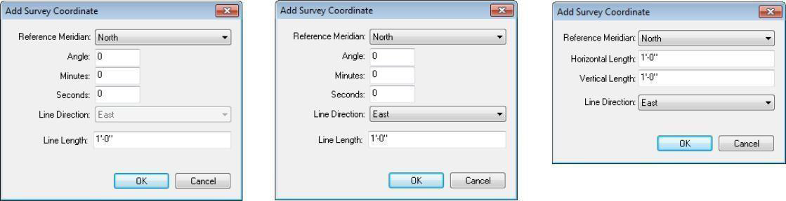
Azimuth Bearing Relative
-
Specify the survey coordinates and click OK.
-
Click OK to draw the property line.
Adding a Fill Region
From simple, rectangular garden entryways and flower bed
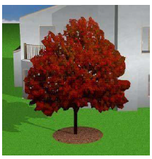
For simple, rectangular garden entryways and flowers beds to elaborate planting areas, Punch! Home Design Software makes designing them easy. You can also show mulch around trees or shrubs, or to add a pond or stream to your landscaping. Ground fill regions have a default mlch material applied which can be updated by applying a different material to the region in the 3D view window. As you draw fills, a rubber band line is displayed and follows the pointer the pointer. Also, dimensions are displayed as you draw.
After you draw a ground fill region, you can change the material that is applied to the fill, or you can fill the region with plants, or even add edging around the border. When filling with plants, you should make sure to give them enough space to account for their gowth potential.
Below are some references that may be helpful as you design:
- Reshaping and Resizing 2D Objects
-
AutoSnap and Alignment Options
-
Elevating Objects
- Moving a Selection & Nudging a Selection
- Changing Curve Tension
- Dimensioning
-
Component Description
-
Applying Building Materials
To add a ground fill region 
- On the Landscape plan toolbar, click the Ground Fill Region Tool.
- On the Properties tab, click the Draw Method drop-down menu and choose the shape you want.
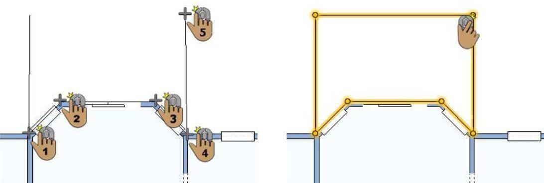
- Use the Define 2D Shape drawing method to draw a fill region.
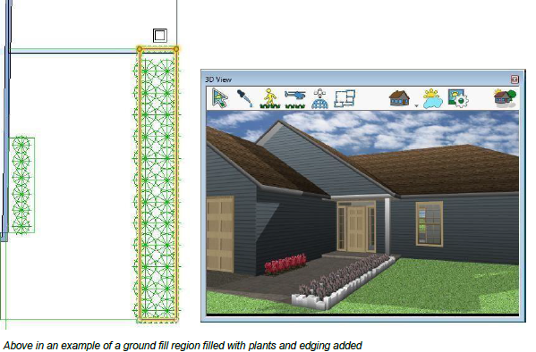
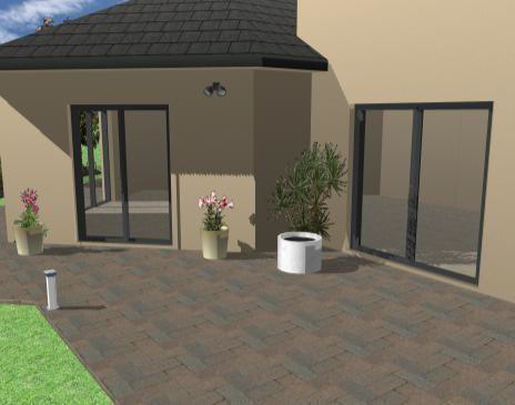
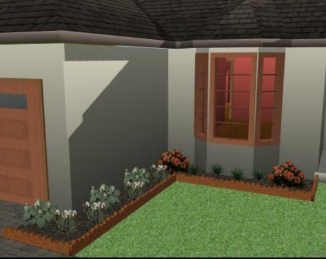
This example shows a ground fill region drawn using the Rectangle From Corner shape
To fill a ground fill region with plants
-
Draw a ground fill region (see “To add a ground fill region”).
-
Choose the plant you want to add in the fill region (for information on accessing plants, see “Plants Libraries”).
-
Right-click an edge of the ground fill region and choose Plant Fill. The Plant Fill dialog box is displayed.
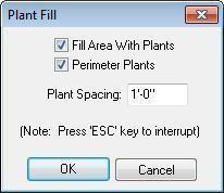
- Choose the settings you want and then click OK.
To add edging around a ground fill region
-
Draw a ground fill region (see “To add a ground fill region”).
-
Right-click an edge of the ground fill region and choose Create Edging Border. To edit the edging, see “Edging Properties”.
Drawing a Patio
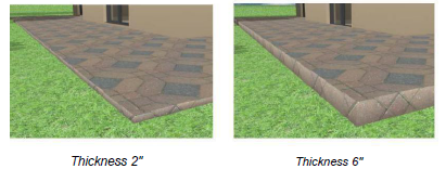
Easily customize your outdoor living space by adding a patio. You can edit the patio thickness on the Properties tab before or after you draw the patio. Patios are drawn with a default material, which you can change by applying a different material.
Below are some references that may be helpful as you design:
- Patio Properties
-
Reshaping and Resizing 2D Objects
-
Elevating Objects
-
Component Description
-
Changing Curve Tension
- Dimensioning
- Applying Building Materials
To add a patio 
- On the Landscape plan toolbar, click the Patio Tool.
- On the Properties tab, click the Draw Method drop-down menu and choose the shape you want.
- Use the Define 2D Shape drawing method to draw a patio.
Patio Properties
Patios are defined by their thickness. You can edit the properties before you draw or after the component has been added to your design by selecting it and clicking the Properties tab.
Note: Always press the ENTER key to accept new values in a text box.
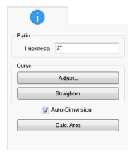
1- Patio Thickness defines the distance from the bottom of the patio section to the top.
-
Curve options control curvature. For more information, see “Changing Curve Tension”.
-
Auto-Dimension checkbox controls the displays of dimensions in 2D. If automatic dimensions are not displayed for the entire drawing, the stair dimensions are not displayed. For details on controlling the automatic dimensions display “Dimensioning”.
-
Calc. Area button automatically calculate the square footage of the patio section. The area is displayed on the Properties tab.
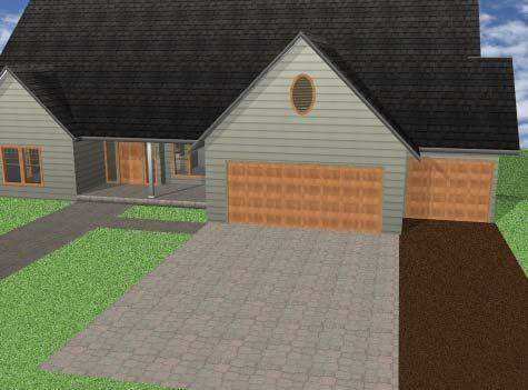
Adding Outdoor Cabinets
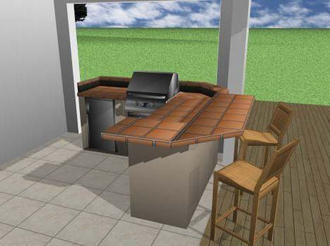
Outdoor Cabinets can be added to your design with just a few mouse clicks. In addition to placing pre-designed cabinets, you can customize each feature as well as create a cabinet of your own from scratch.
When the tool is active you can choose the cabinet style you want from the Properties tab. You can also change the cabinet style after it has been placed in your drawing.
Cabinets are added with default properties, but you can customize almost every aspect of a cabinet to make it your own.
Below are some references that may be helpful as you design:
-
Outdoor Cabinet Properties
-
AutoSnap and Alignment Options
-
Rotating a Selection
-
Elevating Objects
- Moving a Selection & Nudging a Selection
- Applying Paint and Color & Applying Building Materials
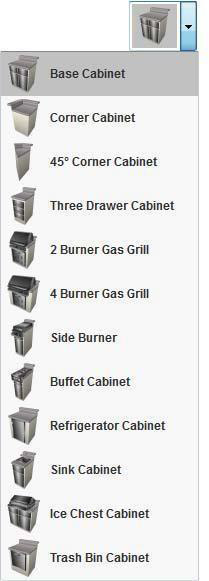
To add an outdoor cabinet 
1- On the Landscape plan toolbar, click the outdoor cabinet tool.
2- Use the Click Once to Place drawing method to place
Outdoor Cabinet Properties
You can easily edit a cabinet after you’ve placed it in your drawing. From resizing base doors to adding additional drawers, each aspect of a cabinet is customizable. To access the different faces and components of a cabinet, click the cabinet Component button on the Properties tab.
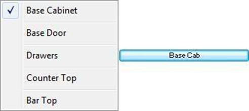
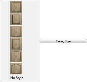
Cabinet Styles
The available properties depend on the cabinet style. You can change the cabinet style at any time as you design
Cabinet Components
The Component button lists the components on the active cabinet style that are available for editing. When you choose one of the components, its properties are displayed on the Properties tab.
The cabinet components that are available for editing depending on the active cabinet style. For example, the Base Cabinet style includes Base Cabinet and Base Door components, while the Gas Grill styles do not include door components. Each of the available Component properties are described below.
Note: Always press the ENTER to accept new values in a text box.
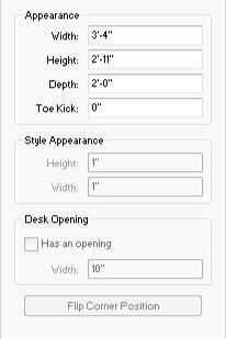
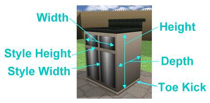
Base Cabinet
-
Width defines the overall distance from one side of the cabinet to the other side.
-
Height defines the distance from the bottom of the base cabinet to the top of the base cabinet.
-
Depth defines the distance from the front side of the cabinet to the back.
-
Toe Kick defines the height of the toe kick, measured up from the bottom of the cabinet.
-
Style Height defines the distance between the top and bottom edges of the doors and drawers and the edges of the cabinet. When this value is adjusted, the size and positioned of the doors and drawers is affected.
-
Style Width defines the distance between the side edges of the doors and drawers and the edges of the cabinet. When this value is adjusted, the size and positioned of the doors and drawers is affected.
-
Desk Opening checkbox controls the whether or not the cabinet includes an opening in the center. When selected, an opening is added, and you can adjust the Width in the corresponding text box. When deselected, an opening is not included.
- Flip Corner Position button flips the corner where the angled outward facing cabinet is positioned to the opposite corner (applies to corner style cabinets only).
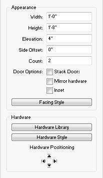
Base Door/Drawers
-
Width defines the distance from one side of an individual door or drawer to the other side.
-
Height defines the distance from the bottom of an individual door or drawer to the top.
-
Elevation defines the distance between the bottom of cabinet and the base of the component.
-
Side Offset defines the distance that the component is positioned from the side of the cabinet.
-
Count defines the number of doors or drawers.
-
Stack Doors/Stack Drawers checkbox controls whether base cabinet doors and drawers are position side-by-side or stacked one on top of the other. When selected, the components are stack on top of each other; when deselected they are positioned side-by-side.
-
Mirror Hardware checkbox controls the position of the door hardware. When selected, all of the hardware is positioned at the same location on each door; when deselected the hardware is positioned in the top corner of the inside edge.
- Inset checkbox controls the display of the door or drawer. When selected, the component is inset as an opening; when deselected the door or drawer is displayed. (available for Base Door and Drawers only).
- Facing Style button provides style options for the door and drawer faces.
-
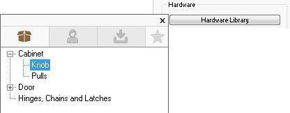
Hardware Library button provides access to the Cabinet Knobs and Pulls libraries.
-
Hardware Style button opens the hardware library styles. When a style is selected it is automatically applied to the hardware.
-
Hardware Positioning allows you to click an arrow to move the hardware in that direction.
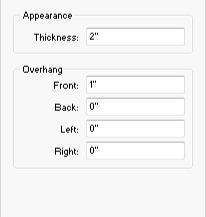
Counter Top
-
Thickness defines the distance from the bottom of the counter top to the top.
-
Overhang Front defines the distance the front edge of the counter top extends out from the cabinet.
-
Overhang Back defines the distance the back edge of the counter top extends out from the cabinet.
-
Overhang Left defines the distance the left edge of the counter top extends out from the cabinet.
-
Overhang Right defines the distance the right edge of the counter top extends out from the cabinet.
Bar Top
-
Backsplash Height defines the distance backsplash extends up from the cabinet.
-
Backsplash Depth defines the distance from the front of the backsplash to the back of the cabinet.
-
Left, Right, and Back Visible checkboxes control the visibility of the backsplash on that corresponding side. When selected, a backsplash is visible on that edge; when deselected it is not visible.
-
Thickness defines the distance from the bottom of the bar top to the top.
-
Back Depth defines the distance the bar top extends away from the back of the cabinet.
-
Left Depth defines the distance the bar top extends away from the left backsplash (Left backsplash must be enabled).
-
Right Depth defines the distance the bar top extends away from the right backsplash (Right backsplash must be enabled).
Drawing Sidewalks, Pathways and Driveways
In Punch! Home Design Software, you can design sidewalks, pathways, and driveways using the same tool. Once a pathway is drawn, you can customize it by applying any material to suit your needs.
By default, the pathway is drawn using a curved style. You can change this, as well as the width, on the Properties tab before or after you draw.
Pathways are drawn with a default material, which you can change by applying a different material.
Below are some references that may be helpful as you design:
- Pathway/Driveway Properties
-
Reshaping and Resizing 2D Objects
-
AutoSnap and Alignment Options
-
Elevating Objects
- Moving a Selection & Nudging a Selection
- Component Description
- Applying Building Materials & Applying Paint and Color
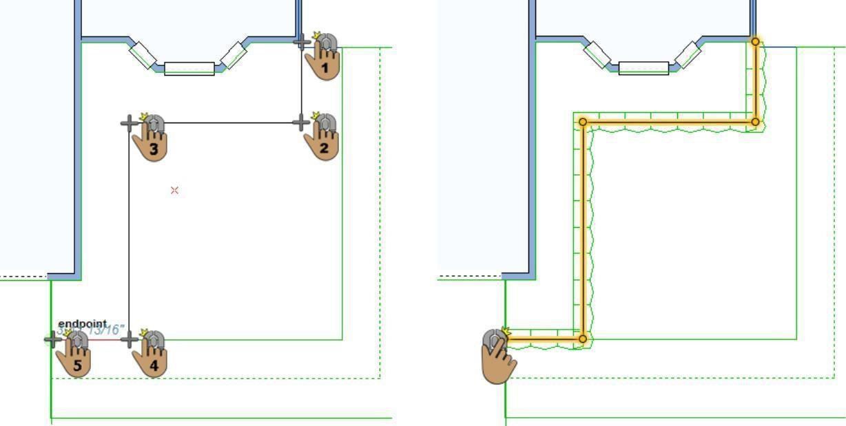
To add a pathway 
-
On the Landscape plan toolbar, click the Pathway/Driveway Tool.
-
In the design window, click to set the start point and drag to define the shape of the pathway or driveway.
-
Continue to click points and drag to define the shape of the pathway or driveway and then right- click to place.
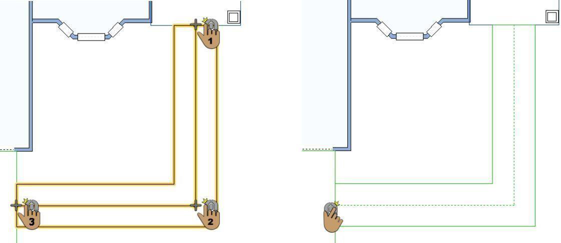
In this example the width is 4'-0" and the Style is Straight.
Pathway/Driveway Properties
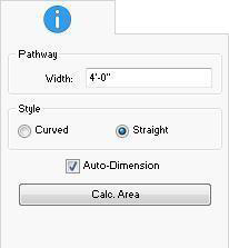
Pathways and driveways are defined by their width and whether they are curved or straight. You can edit the properties before you draw or after the component has been added to your design by selecting it and clicking the Properties tab.
Note: Always press the ENTER to accept new values in a text box.
-
Pathway Width defines the distance from one side of the pathway to the other side.
-
Pathway Style specifies a curved or straight pathway.
-
Auto-Dimension checkbox controls the displays of dimensions in 2D. If automatic dimensions are not displayed for the entire drawing, the pathway dimensions are not displayed. For details on controlling the automatic dimensions display “Dimensioning”.
-
Calc. Area button automatically calculate the square footage of the pathway. The area is displayed on the Properties tab.
Adding Edging
Punch! Home Design Software makes it easy to place edging around flower beds or along walkways. Once drawn, you can apply colors or materials to the edging so it blends with your home plan’s color scheme.
Edging is drawn with a default material, which you can change by applying a different material. You can also edit the edging properties on the Properties tab before or after you draw.
Below are some references that may be helpful as you design:
- Edging Properties
-
AutoSnap and Alignment Options
-
Reshaping and Resizing 2D Objects
-
Elevating Objects
- Moving a Selection & Nudging a Selection
- Applying Building Materials & Applying Paint and Color
To add edging 
- On the Landscape plan toolbar, click the Edging Tool.
- On the Properties tab, click the Draw Method drop-down menu and choose the shape you want.
- Use the Define 2D Shape drawing method to draw edging.
Edging Properties
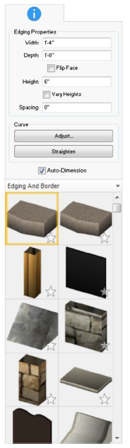
Edging is defined by its width, depth, height, spacing, and the style. You can edit the properties before you draw or after the component has been added to your design by selecting it and clicking the Properties tab.
Note: Always press the ENTER to accept new values in a text box.
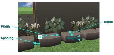
1- Edging Width defines the distance from one side of a apiece of edging material to the other side of a piece of edging.
2- Edging Depth defines the distance from the front of the edging to the back.
3- Flip Face allows you to flip the front and back edges of the edging.
4- Edging Height defines the distance from the base of the edging to the top.
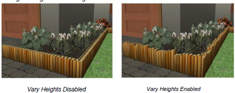
Vary Heights when selected the edging is displayed with ragged, varied heights along the entire segment. When deselcted, the edging is the same height along the entire segment.
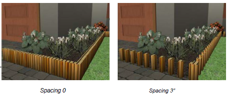
5- Edging Spacing defines the distance between each piece of edging material.
6- Curve options control curvature. For more information, "Changing Curve Tension"
7- Auto-Dimension checkbox contols the displays of dimensions in 2D. If automatic dimensions are not displayed for the entire drawing, the edging dimensions are not displayed. For details on controlling the automatic deimsion display, "Dimensioning"
- Styles library includes the available edging and border styles. You can choose the style before or after you place the edging.
Drawing Fences and Gates
With Punch! Home Design Software, you can draw fences and gates with ease. Once a fence or gate is drawn, you can customize it by applying any material or paint color.
The following options are available from the Fence toolset:
-
Fence
-
Fence Gate
Below are some references that may be helpful as you design:
- Fence and Gate Properties
-
Reshaping and Resizing 2D Objects
-
AutoSnap and Alignment Options
-
Elevating Objects
-
Rotating a Selection
- Applying Paint and Color & Applying Building Materials
Fence
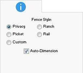
Fences are drawn to follow your topography. When the tool is active you can choose the style, you want from the Properties tab. You can also change the style after the fence has been placed by selecting the fence in your drawing and choosing a different style.
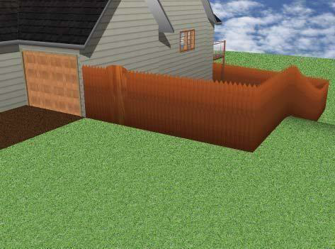
The pre-configured fence styles have set measurements that cannot be changed. To add a fence that you can edit, either before or after you draw, choose the Custom fence option on the Properties tab.
This is an example of a Custom fence with an Iron Ornamental material applied
To add a fence 
-
On the Landscape plan toolbar, click the Fence Tool from the Fence toolset.
-
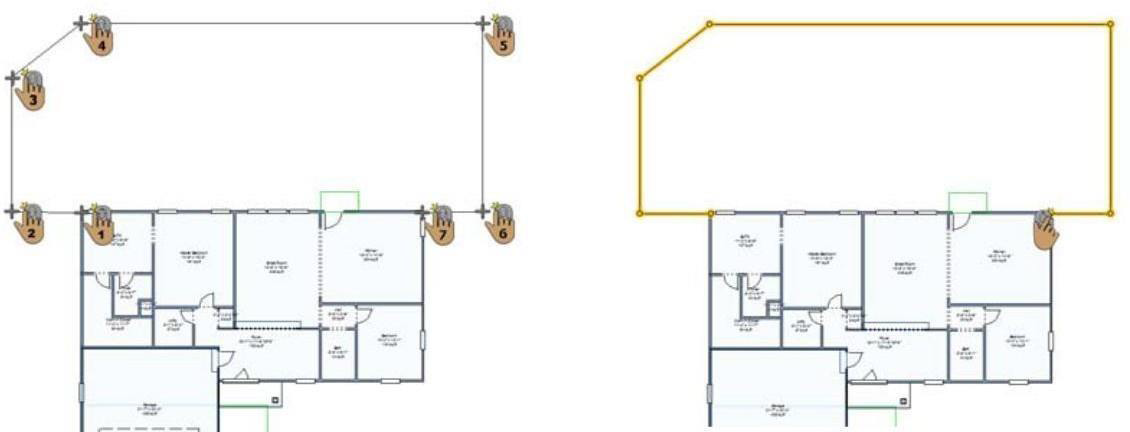
In the design window, click to set the start point and drag to define the shape of the fence.
-
Continue to click points and drag to define the shape of the fence and then right click to place.
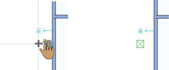
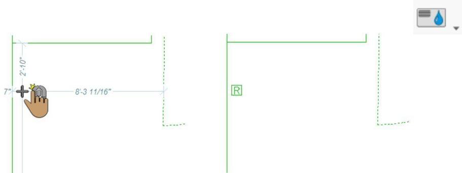
Fence Gate
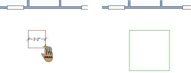
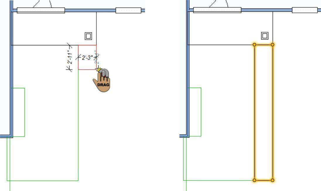
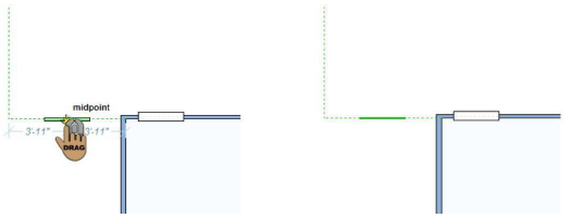
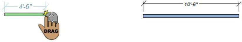
Using the Gate Tool, you can add a gate along a fence segment. The gate style always conforms to the fencing material, so if a gate is placed on a privacy fence, the gate will be a privacy fence gate. You can set the gate width on the Properties tab before you add it, or by dragging its end points after you’ve added it in your design.
To add a gate to a fence
1- On the Landscape plan toolbar, click the gate tool from the fence toolset
2- Use the drag along wall drawing method to position the gate on the fence and release to place.
Fence and Gate Properties
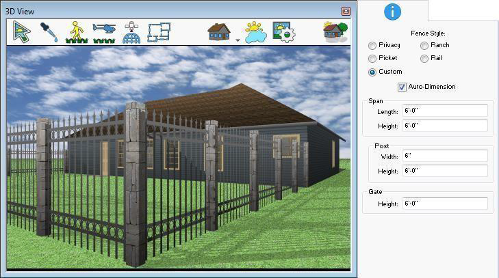
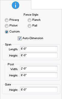
The properties that are available for a fence depend on the fence style. Pre-configured fence styles have set dimensions that cannot be edited. The Custom fence style is defined by the span length and height, post width and height, and the gate height. Gates inherit the fence style.
Note: Always press the ENTER to accept new values in a text box.
Fence Styles
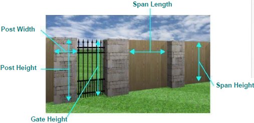
Custom Style
-
Span Length defines the length of each section in the run of the fence.
-
Span Height defines the distance from the bottom of the fence section to the top.
-
Post Width defines the distance from one side of the post to the other side.
-
Post Height defines the distance from the bottom of the post to the top.
-
Gate Height defines the distance from the bottom of the gate to the top.
Drawing Retaining Walls
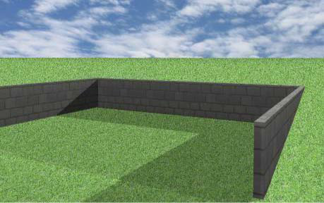
Punch! Home Design Software makes it easy to add interest and functionality to your outdoor living areas by adding retaining walls. Retaining walls can be used to create raised planting beds, to line an above-ground swimming pool, to separate two varied height areas in a lot, and more.
When the tool is active you can choose the wall style you want from the Properties tab. You can also change the wall style after it has been placed in your drawing.
Below are some references that may be helpful as you design:
- Retaining Wall Properties
-
2D Editing Methods
-
Elevating Objects
-
Reshaping and Resizing 2D Objects
-
Changing Segment Length
-
Customizing Wall Framing Properties
- Applying Paint and Color & Applying Building Materials
To add a retaining wall 
- On the Landscape plan toolbar, click the Retaining Wall Tool.
- Use the Click-and-Drag drawing method to set the angle and length for the retaining wall.
Retaining Wall Properties
Retaining walls are defined by their wall style, thickness, height, and in some cases their slope. For more information on editing walls, see “Wall Properties”.
Designing a Sprinkler System
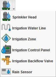
Punch! Home Design Software will be useful to design a sprinkler system for your yard. All of the irrigation tools are available from the Irrigation toolset on the Landscape plan tab.
Below are some references that may be helpful as you design:
■ Reshaping and Resizing 2D Objects
■ AutoSnap and Alignment Options
■ Elevating Objects
■ Rotating a Selection
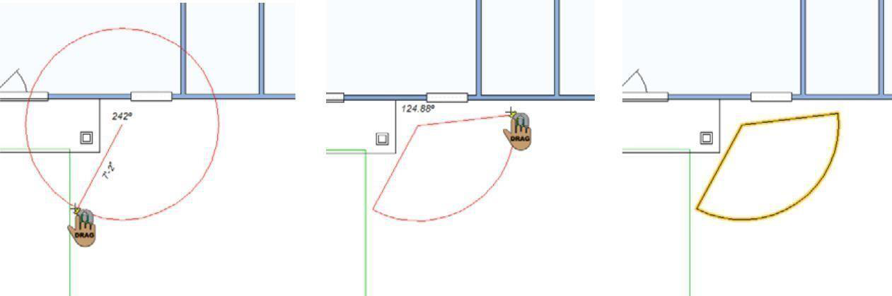
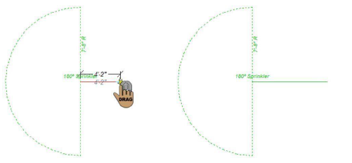
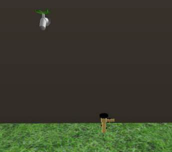
Sprinkler Head
By placing a series of sprinkler heads, with various coverages, you will achieve a complete watering pattern. Sprinklers are visible in the 2D view only.
To add a sprinkler head 
-
On the Landscape plan toolbar, click the Sprinkler Head Tool from the Irrigation toolset.
-
Use the Click-and-Drag drawing method to define the radius and then drag to specify the coverage area for the sprinkler. Release to place.
Irrigation Water Line
Water lines are used to represent the connections in an irrigation system. These are visible in the 2D view only.
To add an irrigation water line 
1- On the Landscape plan toolbar, click the Irrigation water line tool from the irrigation toolset.
2- Use the Click-and-Drag Drawing method to set the angle and length for the component
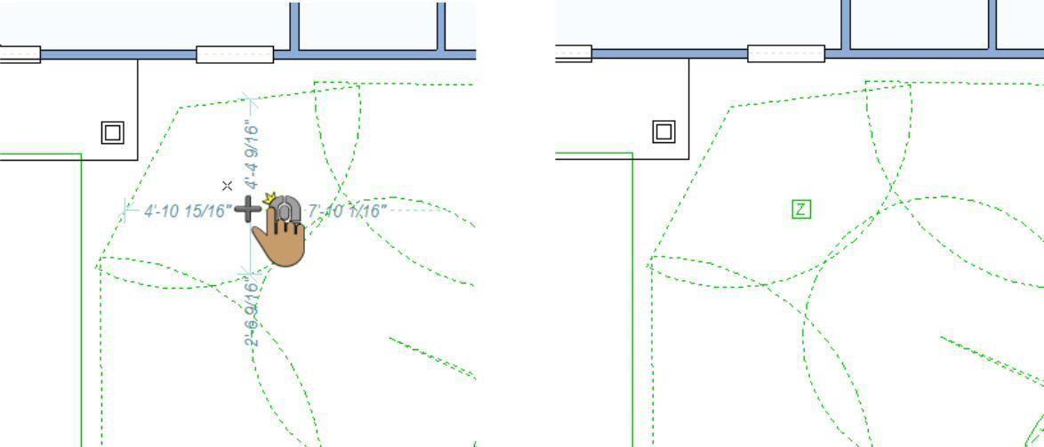
Irrigation Zone
Irrigation zone markers provide a 2D representation of the various zones in your irrigation system.
To add an irrigation zone 
- On the Landscape plan toolbar, click the Irrigation Zone Tool from the Irrigation toolset.
\2. Use the Click Once to Place drawing method to place each zone in your design.
Irrigation Control Panel
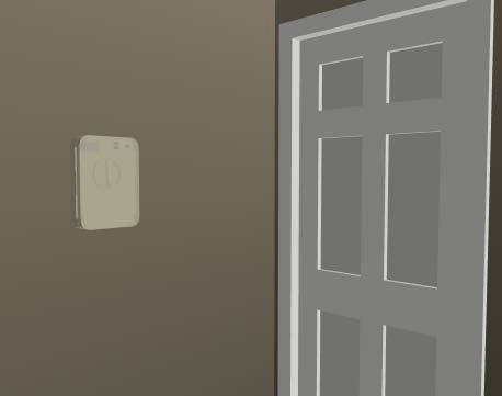
You can add an irrigation control panel to a wall in your design. Once placed, you can reposition or adjust the elevation of the control panel.
To add an irrigation control panel 
- On the Landscape plan toolbar, click the Irrigation Control Panel Tool from the Irrigation toolset.
- Use the Drag Along Wall drawing method to position the control panel on the side of a wall where you want it and release to place.
Irrigation Backflow Valve
Backflow valves can be an integral part of your irrigation system, and in some case, a legal requirement. You can easily add backflow values to your design and see them in both the 2D and 3D views.
To add an irrigation backflow valve 
- On the Landscape plan toolbar, click the Irrigation Backflow Valve Tool from the Irrigation toolset.
- Use the Click Once to Place drawing method to place each valve in your design.
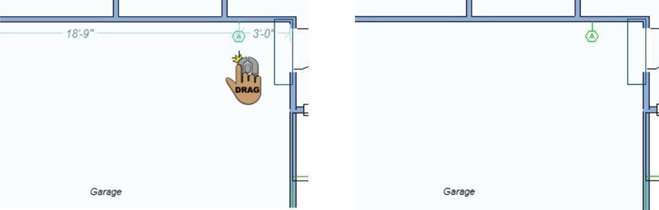
Rain Sensor
You can place rain sensors to help increase the efficiency of your irrigation system and conserve water and energy, when possible. Place rain sensors in a location that is unobstructed by overhangs or branches for an accurate measurement.
To add a rain sensor
- On the Landscape plan toolbar, click the Rain Sensor Tool from the Irrigation toolset.
- Use the Click Once to Place drawing method to place each sensor in your design.
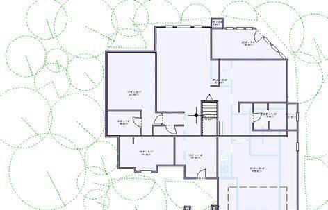
Drawing Topography Elements
You can draw contours lines to represent the topography of your lot. Contour lines represent a series of connected points that share the same elevation. You begin by choosing a general shape for your contour, setting the elevation, and then choosing the drawing method. When used together, multiple lines set at varying elevations creates dips or berms in your landscape.
The contour tools are available from the Topography toolset on the Landscape plan tab.
When the tool is active you can set the topography line elevation on the Properties tab. You can also change the elevation of the topography line after it has been placed in your drawing.
There are a number of drawing methods for creating topography. The default shape is a polygon, which you can draw as an enclosed or open shape. For details on draw methods, see “Detail Plan Tab”. Below is an example of using topography lines to create a berm, where the inner contour lines are set to higher elevations.
Note: Elevations for topography are not cumulative, each is relative to the working elevation of your drawing. Below are some references that may be helpful as you design:
-
Topography Element Properties
-
AutoSnap and Alignment Options
-
Reshaping and Resizing 2D Objects
To add topography lines 
- On the Landscape plan toolbar, click the Topography Line Tool from the Topography toolset.
- On the Properties tab, click the Draw Method drop-down menu and choose the shape you want.
- Use the Define 2D Shape drawing method to draw the topography.
This example shows a railing drawn using the Closed Curve Polygon shape
Topography Element Properties
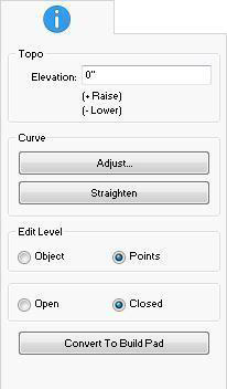
Topography elements are defined by their shape and elevation. You can edit the properties before you draw or after the element has been added to your design by selecting it and clicking the Properties tab.
Note: Always press the ENTER to accept new values in a text box.
-
Elevation defines the elevation at which the contour line is positioned, relative to the ground.
-
Curve options control curvature. For more information, see “Changing Curve Tension”.
-
Edit Level Select Object to resize the whole object or Points to edit individual points on the shape.
-
Open & Closed options specify if the shape is open-ended or contained. When closed, the elevation applies to the entire contour creating more of a full shape; when open the contour blends with the lower elevation at the opening creating a shallower shape.
-
Convert to Build Pad button creates a flat area regardless of topography lines that exist.
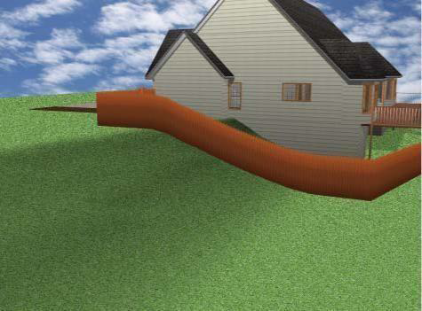
Adding Slopes
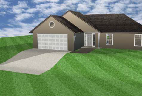
Many topographical maps show slopes, rather than complex topography shapes. Once you’ve defined the slope, you can move selected topography lines to create plateaus or otherwise customize your topography design.
You can set the start elevation for the slope and the descent angle before you draw or after the component has been added to your design by selecting it and clicking the Properties tab.
Below are some references that may be helpful as you design:
-
Slope Lot Properties
-
AutoSnap and Alignment Options
-
Reshaping and Resizing 2D Objects
To add a slope to the landscape 
-
On the Landscape plan toolbar, click the Slope Lot Section Tool from the Topography toolset.
-
Use the Click-and-Drag drawing method to set the descent angle and length for the slope.
Slope Lot Properties
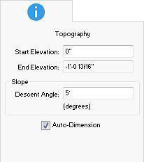
Slope lots are defined by their starting and ending elevations. You can also choose to specify a descent angle.
Note: Always press the ENTER to accept new values in a text box.
- Start Elevation defines the elevation where the top of the slope begins. The slope descends from this elevation.
- Descent Angle defines the angle of the slope.
- Auto-Dimension checkbox controls the displays of dimensions in 2D. If automatic dimensions are not displayed for the entire drawing, the slope dimensions are not displayed. For details on controlling the automatic dimensions display “Dimensioning”.
Excavating Topography
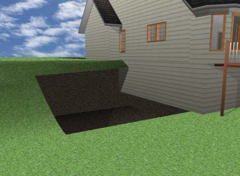
From underground barns to planting cavities, you can excavate with ease.
By default, excavated areas are created at an elevation of -3'-0", meaning 3'-0" into the ground. The elevation is controlled by the component elevation setting in the Elevation bar.
You can further customize excavations using the following edit methods:
- Elevating Objects
-
Reshaping and Resizing 2D Objects
-
Selecting Points and 2D Shapes
-
AutoSnap and Alignment Options
-
Rotating a Selection
- Moving a Selection & Nudging a Selection
- Changing Curve Tension
To excavate the topography 
- On the Landscape plan toolbar, click the Excavate Topography Tool from the Topography toolset.
- On the Properties tab, click the Draw Method drop-down menu and choose the shape you want.
- Use the Define 2D Shape drawing method to draw an excavated area.