Control 3D Options
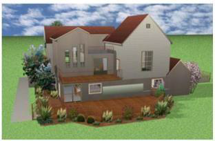
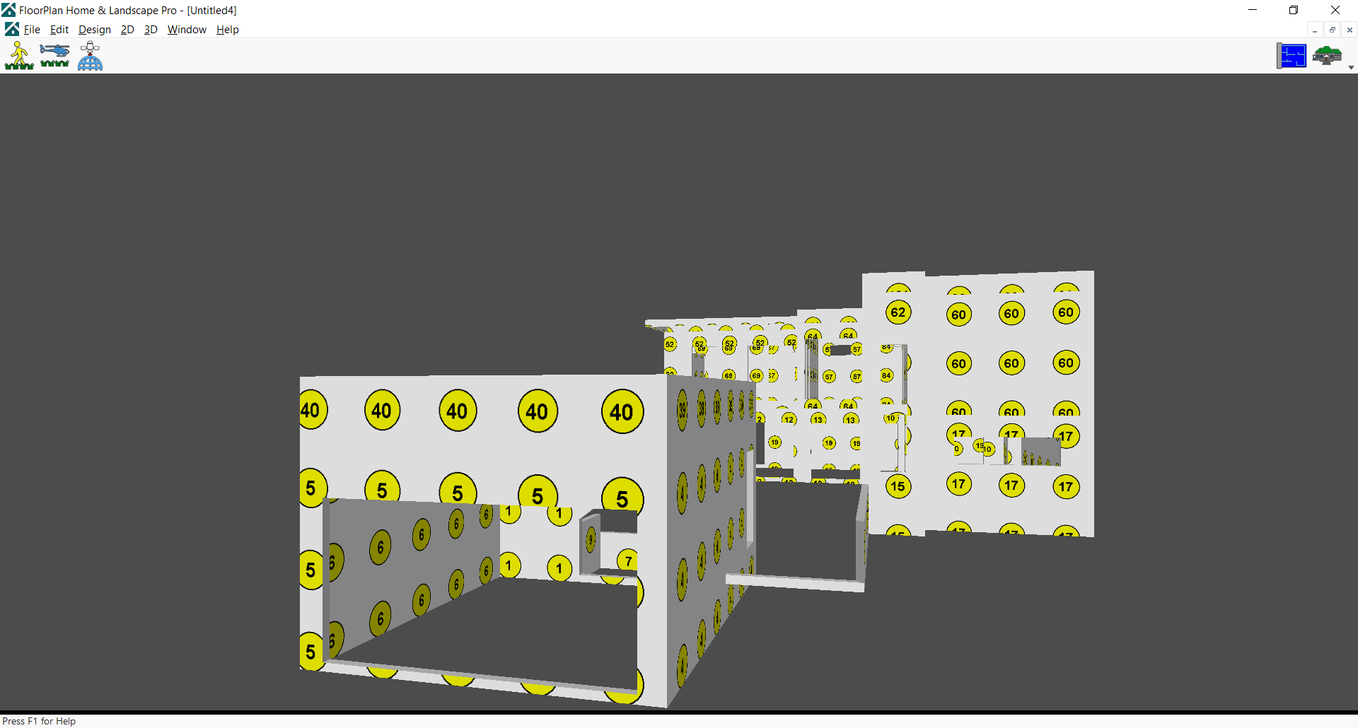
FloorPlan Software lets you view your design in a fully-rendered 3D view. You can select exterior and interior wall color, add realistic roof materials and select from a variety of wood textures to make your design completely unique. In the 3D View window, you can view your design from a variety of angles.
Using Decorator Palettes, you can easily make changes to your decorating theme. This makes it easy to experiment with a variety of color schemes, both inside and outside your design, before picking up a paintbrush!
With the powerful ClearView feature, you can literally see through the walls and view electrical, plumbing, and so on.
FloorPlan Software integrates the exclusive, patented RealModel® technology, making it easy to construct an actual scale model of any home you draw. Once you have completed your home design, details are automatically transferred to RealModel. Instructions on building your home model are printed, with numbered sections and floor plan templates that make assembling it simple. This hands-on model shows you how to improve your design and save on construction costs before you break ground. This is the perfect tool for presenting your ideas to your builder or architect.
FloorPlan Software provides interactive 3D viewing options, including the 3D Walk-Through and Fly- Around views, as well as an over-head aerial view and a room view, to focus on selected rooms in the design. Using interactive viewing, you can vary the viewing level by adjusting the altitude and height. Viewing speed and camera angle can also be adjusted to provide the best viewing capabilities available.
To navigate using walk-through 
Using the Walk-Through Tool, you can navigate your design as if you were walking through it. You can navigate the exterior, walk through rooms, and even adjust the viewing elevation to change floors.
- Open a 3D View window and click the Walk-Through button.
(alternatively) Click 3D menu > 3D Navigation > Walk-Through to enable walk- through mode.
- Position the cursor in the 3D view then click-and-drag in the direction you want to move. Right-click and drag left or right to pan in that direction in 3D.

You can adjust the walk-through view in the 2D design window using the Viewpoint icon. The Viewpoint icon represents the position from which you’re viewing the 3D view. Drag the Viewpoint center point to a new location in the design window to update the 3D view and drag the arrow around the center point to rotate the view. You may need to zoom out in the 2D view to find the Viewpoint icon initially.
To adjust your walk-through elevation
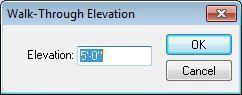
The default walk-through elevation is 5-0. You can adjust the walk-through elevation in two ways:
- Press the right mouse button down and drag up in the 3D view to raise the viewing elevation; drag down to lower the elevation.
(alternatively) Click 3D menu > 3D Navigation > Walk-Through Elevation and type a new elevation measurement, in inches, then click OK.
To view your design using Fly-Around 
Using the Fly-Around Tool, you can navigate your design as if you were flying around it. This gives you a bird’s- eye view of your exterior. You can even adjust the viewing elevation to get a closer look at some areas or see the bigger picture.
-
Open a 3D View window and click the Fly-Around button. (alternatively) Click 3D menu > 3D Navigation > Fly- Around.
-
Position the cursor in the 3D View window then click-and-drag in the direction you want to move.
To change Fly-Around altitude with the mouse
- Press the right mouse button down to change the viewpoint.
To specify a center of reference in Fly-Around mode 
- Open a 3D View window and, on the design window, click the center of reference icon and drag it to a new position.
Note: The placement of the icon will be the point that the helicopter revolves around.
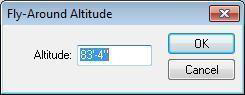
To specify an absolute Fly-Around altitude
- Click 3D menu > 3D Navigation > Fly-Around Altitude. The Fly-Around Altitude dialog box is displayed.
-
Type a new elevation measurement, then click OK.
-
Open a 3D View window and navigate, as explained previously.
To see an aerial or bird’s eye view of your design 
-
Open a 3D View window and click the Aerial View button (alternatively) Click 3D menu > 3D Navigation > Aerial View.
-
Position the cursor in the 3D View window then click-and-drag to pan or press your arrow keys to nudge the aerial view.
To rotate your aerial view, press the right mouse button down and drag your mouse.
To change your aerial view elevation
- Press and hold your right mouse button to toggle your aerial view elevation.
To see a room, view of your design
-
Open a 3D View window so you can see the 2D and 3D views.
-
Click to select the room(s) you want to view. You can use the Selection Tool in the 2D or 3D view.
Note: You can press SHIFT while clicking to select multiple rooms in 2D.
- Click the Room View button on the 3D View window. The 2D and 3D views are updated to focus on the selected room(s).

(alternatively) Click 3D menu> 3D Navigation > Room View. The 2D and 3D Views are updated to focus on the selected room(s).
- To navigate, press your left mouse button and drag to pan or press your arrow keys to nudge the aerial view.
With the right mouse button down, drag your cursor to rotate your aerial view.
To adjust the 3D camera angle
- Click 3D menu > 3D Rendering > Rendering Options. The Design Options dialog box opens to the Navigation & Render Quality settings.
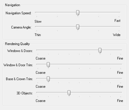
- Under the Navigation section, drag the Camera Angle slider to make the view thinner or wider and then click OK.
To increase or decrease the Fly-Around and Walk-Through speed
-
Click 3D menu > 3D Rendering > Rendering Options. The Design Options dialog box opens to the Navigation & Render Quality settings.
-
Under the Navigation section, adjust the Speed slider and then click OK.
Note: The faster the viewing speed, the lower the quality of the rendered 3D image.
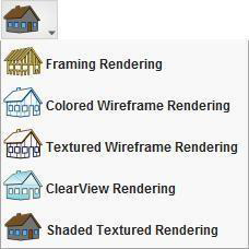
Accessing the 3D Rendering Styles
With FloorPlan Software’s five 3D rendering options you can view your design in a variety of ways.
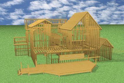
Framing Rendering style displays your design to show the studs, rafters, and other framing components.
 To make framing changes, see “Framing Plan Tab”
 Colored Wireframe displays your design on a white background. Each feature of your floor plan is rendered in the color of the plan tab where it is drawn. For example, walls are displayed in the color you have defined for the Floor Plan tab.
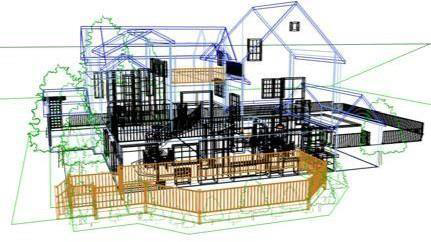
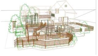
Textured Wireframe also displays your design on a white background. Each feature of your floor plan is rendered in the color of the material you have applied to it.
ClearView may reveal potential conflicts hidden by walls, for example between utilities.
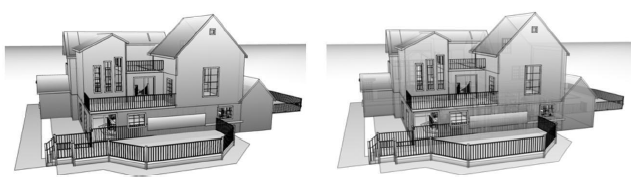
To control the opacity of a ClearView rendering, click Design menu > Options and under 3D Preferences, click General. The settings are displayed in the right pane. Drag the Clearview Opacity slider to adjust its appearance.
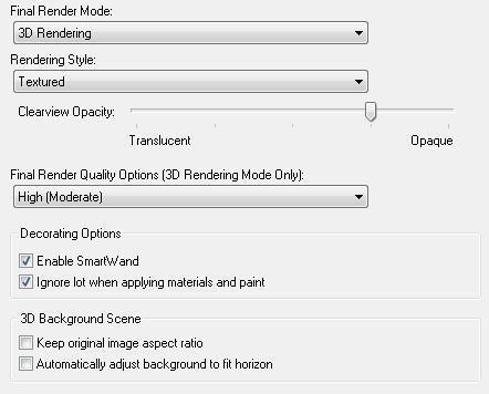
Shaded Textured Rendering must be enabled for these styles to be available.
To view a 3D rendering style
-
Click 3D menu > Rendering Mode > 3D Rendering and then open a 3D View window.
-
In 3D View window, click the Render Style button, then choose the rendering style you want.
(alternatively) Click 3D menu > 3D Rendering >
Rendering Style and choose the style you want.
Adjusting Rendering Quality
FloorPlan Software technology includes anti-aliased. With this technology, you can view your plan with incredible detail, whether you are in ClearView, viewing materials, viewing framing, or using another render style.
To render a 3D preview 
- Open a 3D View window and click the Render Preview button in the 3D View window.
To render a plan in 3D final quality
- Open a 3D View window and click 3D Menu > 3D Rendering > Render Final Quality.
To set 3D render quality
- Click 3D menu > 3D Rendering > Final Quality Options and choose one of the options. Note: You can stop the rendering process at any time by pressing ESC.
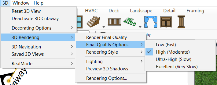
- Low results in a fast rendering speed, but lower quality output.
- High results in a moderate rendering speed and average quality output.
- Ultra High results in a slower rendering speed and a high-quality output.
- Excellent results in a very slow rendering speed, but a very high quality, sharp output.
Setting Rendering Options
With FloorPlan Software you can customize the render quality of many of the customized features you use.
By setting these features to a lower render quality, you can speed up the rendering time.
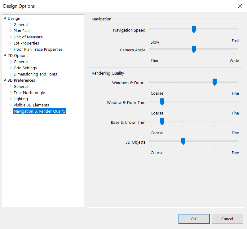
To set the render options
- Open a 3D View window and click the Navigation and Rendering Options button on the 3D View window. The Design Options dialog box opens to the Navigation & Render Quality settings
(alternatively) Click 3D menu > 3D Rendering > Render Options.
- Drag the sliders to set the rendering quality for each feature you want to change and then click
OK. Note: The lower the render quality is set, the faster 3D View will render your design.
To adjust lighting settings 
1. Open a 3D View window and click the 3D
Lighting button on the toolbar. The Design Options dialog box opens to the Lighting settings
(alternatively) Click 3D menu > 3D Rendering > Lighting > Lighting.
- Edit the settings as needed and then click OK.
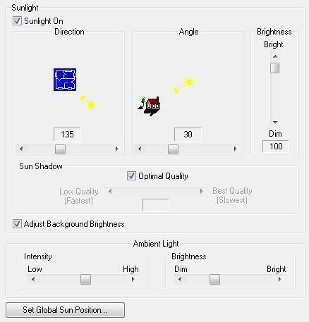
- Sunlight On checkbox enables all of the sunlight settings in the 3D when selected; the sunlight settings are ignored when deselected.
- Direction slider controls the direction from which the sun shines. Drag the slide to position the sun around the plan.
- Angle slider controls the sun’s angle in the sky. Drag the slider to adjust the angle from which the sun shines.
- Brightness slider increases or decreases the sun’s brightness. Drag to adjust the brightness as needed.
- Sun Shadow settings are disabled when Optimal Quality is selected. To edit the settings, deselect the Optimal Quality checkbox and drag the slider to change the sun’s shadow quality. (A lower shadow quality speeds up rendering times, while a higher quality slows down rendering times.)
- Adjust Background Brightness checkbox controls if the background image is affected by the Sunlight or Ambient Light settings. When selected, lighting settings affect the background as well; when deselected the background is not updated when lighting settings are changed.
- Ambient Light is controlled by the Intensity and Brightness settings. Drag the sliders to increase or decrease the settings.
To adjust lighting to daytime
-
Open a 3D View window, as explained previously.
-
Click 3D menu > 3D Rendering > Lighting > Adjust Lighting to DayTime. All of the light fixtures are turned off, and your design is displayed as if it is daytime.
To adjust lighting to nighttime
-
Open a 3D View window, as explained previously.
-
Click 3D menu > 3D Rendering > Lighting > Adjust Lighting to NightTime. All of the light fixtures are turned on, and your design is displayed as if it is nighttime.
To turn all light fixtures on
-
Open a 3D View window, as explained previously.
-
Click 3D menu > 3D Rendering > Lighting > All Light Fixtures ON. All of the light fixtures in your design turn on.
To turn all light fixtures off
-
Open a 3D View window, as explained previously.
-
Click 3D menu > 3D Rendering > Lighting > All Light Fixtures OFF. All of the light fixtures in your design turn off.
To render shadows to a 3D view
-
Open a 3D View window, as explained previously.
-
Click 3D menu > 3D Rendering > Preview 3D Shadows.
Note: Shadows are also rendered when the Render Final Quality selection is clicked.
Using the Decorator Palette
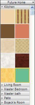
FloorPlan Decorator Palette allows you to construct lists of commonly-used colors and materials so they can be easily used throughout your design. Each palette is divided into as many as 15 groups, allowing you to assign each group to a room or other segment of your design.
You simply load the Decorator Palette with the colors and materials you want to apply to your 3D view, then save the palette for use in later sessions. Decorator Palettes can even be exported and imported for use in different drawings.
To build a palette
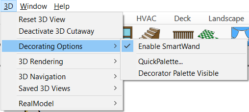
- Click 3D menu > Decorating Options > Decorator Palette Visible. The default palette is displayed.
- Drag-and-drop a color or material onto a blank palette tile.
Applying colors and materials from palette
- Drag-and-drag the color or material you want from the palette tile to an area of your design. Your selection is displayed in 3D View.
To clear a palette entry
-
Right-click the entry you want to delete and choose Clear Palette Entry.
-
Click Yes at the prompt to remove the entry.
Identifying Colors and Materials from the Decorator Palette
When you’re working with a lot of different colors and materials, it can become difficult to remember the library where each appears. You can find a color or material’s original library with just a few simple clicks.
To select a color or paint
- Right-click the color or paint in the palette and click Select Color/Paint from the context menu. Its original library is displayed on the Preview Bar, with the color or paint selected.
To select a material
- Right-click the material in the palette and click Select Material from the context menu. Its original library is displayed on the Preview Bar, with the material selected.
Managing Decorator Palette Groups
You can organize the colors and materials of each room by assigning groups. Decorator Palette provides you with 15 blank group labels.
To create a group
-
Select a material or color you want to add to the palette and then drag-and-drop the color or material onto a blank palette tile. Repeat with additional materials or colors, as desired.
-
Once you have all the materials and colors you want, click the Group 1 label, then choose Rename Section on the drop-down menu. The Palette Section Name dialog box is displayed.

- Type a name for the group in the Palette Section Name text box and click OK. The name you entered is displayed in the group label.
To collapse a group
- Click the group label and choose Collapse Section. The group collapses and displays only its assigned name.
(optional) Click the minus box on the group label.
To expand a group
- Click the group label and choose Expand Section. The group expands and displays your entries. (optional) Click the plus box on the group label.
To expand all groups
- Click the group label and choose Expand All. All of your groups expand and display your entries.
To collapse all groups
- Click the group label and choose Collapse All. All of your groups collapse and display only their assigned names.
Managing Decorator Palettes
Your Decorator Palettes are saved separately from the rest of your design. That means you can use the same palette in different drawings, different sessions, or even share palettes with colleagues.
To save a custom palette
- Click the palette drop-down menu and choose Add Copy of Current Palette. The Palette Name dialog box is displayed.
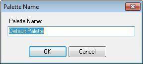
- Specify your palette by typing a name in the Palette Name text box and click OK. Your palette is saved and the name of your palette is displayed.
To import a custom palette
-
Click the palette drop-down menu and choose Import Palette. The Open dialog box is displayed.
-
Click the palette you want to import and click Open. The Palette Name dialog box is displayed.
-
Type a new Palette Name if you want to, then click OK. The palette is displayed.
To export a palette
-
Click the palette drop-down menu bar and choose Export Palette. The Save As box is displayed.
-
To select a different drive or folder, click a different drive and folder, or type the complete path in the File Name text box. Click Save.
Organizing Decorator Palettes
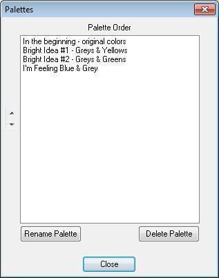
Using the Palettes Organizer, you can prioritize and rename your palettes. You can also delete any palettes you do not want to keep, however at least one palette must remain.
To access the Palettes Organizer
- Click the palette menu and choose Organize Palettes. The Palettes dialog box is displayed with the names of each of your palettes.
To control palette order 
-
Open the Palettes Organizer and click to select the palette you want to reorder.
-
Click the arrow button that corresponds to the direction you want to move the palette. The palette is reordered.
-
Close the Palettes Organizer.
To rename a palette
-
Open the Palettes Organizer and click to select the palette you want to rename. The Palette Name dialog box is displayed.
-
Type the new name in the Palette Name field and then click OK. The palette is renamed.
-
Close the Palettes Organizer.
To delete a palette
- Open the Palettes Organizer and click to select the palette you want to delete. A confirmation dialog box is displayed.
Note: At least one palette must exist.
-
Click Yes to delete the palette. The palette is deleted.
-
Close the Palettes Organizer.
Customizing the 3D View
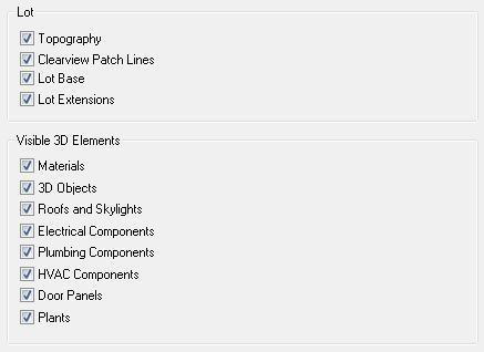
There may be times when you will need to see your design without specific features or objects. With Punch! Home Design Software you have complete control over what parts of your design are visible.
To hide/view specific features in 3D
-
Open a 3D View window, as explained previously.
-
Click Design menu > Options. The Design Options dialog box is displayed.
-
Under 3D Preferences, click Visible 3D Elements. The options are displayed in the right pane.
-
Click to select the features you want to show or deselect the features that you want to hide and then click OK.
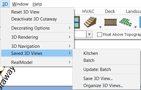
Saving a 3D View
You can save pre-set 3D views that can be easily accessed at any time. The Saved 3D Views menu option is available from the 3D menu. Here, you can save a 3D view and access your saved views. When you save a view, the render style is also saved with the view.
Additionally, you can update a saved view and organize views to rename or delete them.
To save a 3D View
-
Using the 3D navigation tools, set the 3D View window with the direction, angle, and render style that you want to save.
-
Click 3D menu > Saved 3D Views > Save 3D View. The View Name dialog box is displayed.
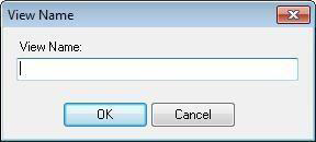
- Type a name for the view in the View Name field and click OK.
To access a saved view
- Click 3D menu > Saved 3D Views and then click the view description on the submenu. The 3D View window displays the selected view.
To update a saved view
-
Open the 3D view you want to edit.
-
Reposition the 3D view as desired and then click 3D menu > Saved 3D Views > Update.
Organizing Saved 3D Views
Using the 3D Views Organizer, you can prioritize, rename, and deleted your saved 3D views.
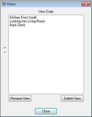
To access the 3D Views Organizer
- Click 3D menu > Saved 3D Views > Organize 3D Views. The 3D Views organizer is displayed.
To control saved 3D view order 
-
Open the 3D Views Organizer and click to select the view you want to reorder.
-
Click the arrow button that corresponds to the direction you want to move the view. The view is reordered.
-
Close the 3D Views Organizer.
To rename a saved 3D view
-
Open the 3D Views Organizer and click to select the view you want to rename.
-
Click the Rename View button. The View Name dialog box is displayed.
-
Type the new name in the View Name field and then click OK. The view is renamed.
-
Close the 3D Views Organizer.
To delete a saved 3D view
-
Open the 3D Views Organizer and click to select the view you want to delete.
-
Click the Delete View button. A confirmation dialog box is displayed.
-
Click Yes to delete the view. The view is deleted.
-
Close the 3D Views Organizer.
Preparing to Construct a RealModel
When constructing a RealModel, you’ll need to get a few supplies together first. Visit your local craft supply or hobby store to purchase these materials.
Items you’ll need to construct a RealModel:
- Construction material — foam board or poster board
- Adhesive — spray adhesive, rubber cement, glue stick, or similar product
- Tape
- Straight pins
-
Straight-edge ruler
-
Artist’s knife or scalpel
To open the RealModel view 
- Click the RealModel View button from the 3D View drop-down menu. The design is displayed in RealModel view.
(alternatively) Click 3D menu > RealModel > Show RealModel.
Defining Scale
The scale you choose will define the actual size of your model. All model templates will print in this scale. For example, if you choose 1/2"=1' - a ten-foot wall will print as a five-inch template.
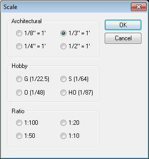
To select RealModel scale
- Show the RealModel view.
- Click 3D menu > RealModel > Model Scale. The Scale dialog box is displayed.
- Click to select the scale you want then click OK.
Printing RealModel Templates
The templates are used to guide you, as you build your RealModel. They will specify which wall section is attached to other walls and where doors and windows are placed.
Floor templates show where each wall is placed. You have the choice of printing all of the wall and roof templates, as well as the template of each floor at one time or printing each element individually.
To edit print settings, see “Printing Floor Plans”.
To print RealModel templates
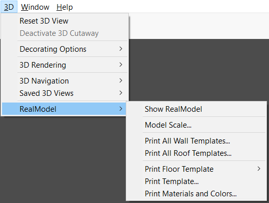
-
Open the RealModel view.
-
Click 3D menu > RealModel and then choose the template you want to print.
-
Print All Wall Templates- Prints all of the walls in the design.
- Print All Roof Templates- Prints all of the roofs in the design.
- Print Floor Template- Choose the floor you want to print from the submenu.
- Print Template- To print an individual template from your design, type the template number you want to print from the RealModel view, then click Print.
The Print dialog box is displayed.
\3. Confirm your default printer selection, then click Print.
Constructing Wall Templates
You will notice that some wall templates will have darker, shaded edges. These shaded areas indicate the thickness of your construction material. Use these as guidelines on where to attach adjoining walls. The directions for connecting the walls will be printed on each page. Be sure to transfer this information to the template, before cutting it out.
To construct a wall template
-
Attach each wall template to your construction material, using a permanent adhesive.
-
Cut out each wall section to the exact size of the template. Be sure to include shaded areas.
-
Attach each template to its appropriate counterpart.
Constructing Roof Templates
Although your roof templates may print attached at points, cut out each roof section separately from your construction material to the exact size of the template.
To construct a roof template
-
Attach each roof template to your construction material, using a permanent adhesive.
-
Cut out each roof section to the exact size of the template.
-
Attach each roof template to its appropriate counterpart.
-
Secure the roof to the walls.
Printing Template Materials and Colors
To add a realistic look to your RealModel, you can print sheets of materials and colors to be applied to your model and trimmed to size. With this process, you can see what your design will look like. Follow these steps for every wall and roof on your model.
Note: It is best to print and assemble the material and color on each wall, before moving on to the next wall. If you choose not to do this, you should label each material template and color, as they are printed, to make identifying them easier, when attaching them to your model.
To print template materials and colors
-
Open the RealModel view. Decide which material you want to print first.
-
Click 3D menu > RealModel > Print Template Materials and Colors. The Print Template Textures & Colors dialog box is displayed.
-
Type the template number of the material and color you want to print, then click Print. The Print dialog box is displayed.
-
Confirm your printer settings, then click Print.
Attaching Template Materials and Colors to Your Model
Once the materials and colors have been printed, you will need to affix them to the appropriate template and trim them to size. It is best to use spray adhesive, glue stick, or tape for this step, as using white glue may cause the paper to wrinkle.
To attach the template materials and colors
-
Affix the material to the proper wall template, which has already been attached to the construction material.
-
Carefully trim around the outside edges of the wall template.
-
Cut out the door and window openings.
-
Attach each template to its appropriate counterpart.