Edit Your Design
In addition to standard Windows commands like cut, copy, paste, and delete, FloorPlan Software includes more sophisticated modes of editing your design. You can copy or move entities, walls, and other design elements, to different floors, as well as between plan layers.
You can flip or mirror your entire design, either vertically or horizontally, to make it easy to visualize various layouts. In addition, you can move or rotate your entire floor plan at one time.
More advanced concepts are also covered here, such as rotating individual entities to custom fit them into your design and elevating entities, using the Elevation Bar, to achieve perfect placement. Learn to customize settings like nudge factor, so FloorPlan Software works best for you.
Undo
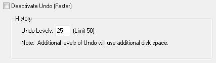
With FloorPlan Software, you can specify up to 50 levels of Undo, making it easy to recover your work. Bear in mind, the more levels of undo you specify, the more system resources will be used. To conserve system resources, set the undo level at the lowest level possible.
To use undo
- Click Edit menu > Undo, or press CTRL+Z. The previous action is reversed.
To turn off undo
- Click Edit menu > Undo Preferences. The Preferences window opens to the Undo Preferences settings.
-
Select the Deactivate Undo checkbox, then click OK. To undo levels
-
Click Edit menu > Undo Preferences. The Preferences window opens to the Undo Preferences settings.
-
Deselect the Deactivate Undo checkbox.
3. Type the number of undo levels you want to use and then click OK.
To use redo
- Click Edit menu > Redo, or press CTRL+Y. The previous action is reversed.
Cut, Copy, and Paste
Cut moves the selection to the Clipboard and deletes the original. Copy places a duplicate of the selection on the Clipboard. Paste places the contents of the Clipboard into your drawing. By default, when you paste a selection multiple times, each time you paste, the element is offset so each is visible. You can also paste a selection without offset, so each time you paste the selection it will stack on top of the previous one. You can place the Clipboard contents as many times as necessary. Clear removes the selection.
To cut a selection
-
On the Edit Toolbar, click the Selection Tool and click the selection you want to cut.
-
Click Edit menu > Cut (or press CTRL+X). The selection is removed to the Clipboard.
To copy a selection to the clipboard
-
On the Edit Toolbar, click the Selection Tool and click the selection you want to copy.
-
Click Edit menu > Copy (or press CTRL+C). The selection is copied to the Clipboard.
To paste a selection from the clipboard
-
On the Edit Toolbar, click the Selection Tool.
-
Click Edit menu > Paste (or press CTRL+V). The selection is copied from the Clipboard to the design window.
To delete a selection
-
On the Edit Toolbar, click the Selection Tool and click the selection you want to delete.
-
Press DELETE on the keyboard.
Nudging a Selection
You can also precisely move features into position using Nudge. Nudge utilizes the arrow keys to move selected features a specified distance, which is based on the Snap Grid settings. To learn more about the Snap Grid and to adjust nudge settings, see “Using the Grid”
Note: To nudge using the Snap Grid settings, Snap to Grid must be enabled. On the 2D Menu, confirm there is a checkmark next to Snap to Grid. This means that the Snap Grid is activated. When the “Snap to Grid” is turned off, Nudge moves the entity or feature one pixel at a time, instead of snapping to the grid distance.
To move a selection using the Nudge feature
-
On the Edit Toolbar, click the Selection Tool then click to select the entity you want to nudge.
-
Use the arrow keys on your keyboard to nudge the entity.
(alternatively) Click Edit menu > Nudge then click the direction (up, down, left, right).
Moving a Selection
Once you’ve placed features, you can move them by dragging or by specifying exact Cartesian or polar coordinates that correspond to the reference grid. For more information on the reference grid, see “Using the Grid”.
Note: To select more than one entity, hold down SHIFT while clicking.
To move entities by dragging
-
On the Edit Toolbar, click the Selection Tool then click to select the entity.
-
Holding down the mouse button, drag the entity to a new location, then release the mouse button.
To move entities by specifying coordinates
-
On the Edit Toolbar, click the Selection Tool then click to select entity.
-
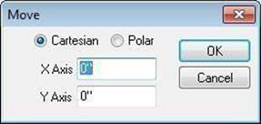
Click Edit > Move. The Move dialog box is displayed.
-
Select either Cartesian or Polar, then type new X and Y-Axis coordinates in the appropriate text boxes.
-
Click OK. The entity you selected is moved, based on the coordinates you specified.
Rotating a Selection 
Using the rotate feature, you can easily spin an entity around any point. This is useful when you want to face an entity in a different direction from which it was drawn. Using the Rotate Tool, you can freely rotate the selection, or you can specify the exact amount of rotation, using the Rotate dialog box. Selections are rotated around their center point.
To freely rotate an entity
-
On the Edit Toolbar, click the Rotate Tool and click to select the point or double-click to select the element you want to rotate.
-
Click-and-drag the entity in the direction that you want to rotate. The degree of rotation is displayed in the Status Bar as you drag.
-
Release the mouse button to place.
To rotate by specifying an amount
-
On the Edit Toolbar, click the Selection Tool and click the feature you want to rotate.
-
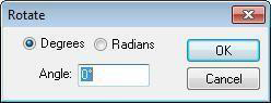
Click Edit menu > Rotate or double-click the Rotate Tool. The Rotate dialog box is displayed.
-
Select either Degrees or Radians, then type the angle you want the selected rotated.
-
Click OK. The entity is rotated.
To rotate an element in 1-degree increments
-
On the Edit Toolbar, click the Selection Tool and click the feature you want to rotate.
-
Press and hold SHIFT, then press the left or right arrow key to rotate the selection in that direction.
Flip and Mirror
The Flip function takes the original feature and reverses it, either horizontally or vertically. Mirror works much like the Flip function. The difference is that Mirror leaves the original and makes a duplicate. Mirror creates two identical entities, facing one another.
To flip a feature horizontally
-
Click the Selection Tool and then click to select the feature you want to flip.
-
Click Edit menu > Flip Horizontal.
To flip a feature vertically
-
Click the Selection Tool and then click to select the feature you want to flip.
-
Click Edit menu > Flip Vertical.
To mirror a feature horizontally
-
Click the Selection Tool and then click to select the feature you want to mirror.
-
Click Edit menu > Mirror Horizontal.
-
Move the feature into position
To mirror a feature vertically
-
Click the Selection Tool and then click to select the feature you want to mirror.
-
Click Edit menu > Mirror Vertical.
-
Move the feature into position.
Aligning Objects
There are a number of options for aligning entities in your drawing. The Align Objects option allows you to align multiple selections with an edge or center of one of the objects.
Align to Grid makes it easy to align a feature or group to a point on the Snap Grid. For more information, see “Using the Grid”.
To align objects to another object
-
Click the Selection Tool and then click to select the object (or objects) you want to be aligned.
-
Press and hold SHIFT and then click the object with which you want the object aligned.
-
Click Edit menu > Align Objects and then click how you want the objects aligned. The objects are aligned with the last object selected, based on the position you chose.
Modify Toolbar
The Modify Toolbar gives you quick access to editing commands. When using the alignment or size matching commands the last object selected will be used as the target alignment or size.
- Alignment tools – Quickly align a selected set of design elements.
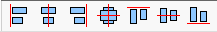
- Distribution tools – Spaces selected design elements evenly.
- Size Match – Make selected elements same width, height or both.
-
Duplicate – Creates specified number of copies, customizable spacing between copies

-
Flip, Mirror – Allows you to flip or mirror design elements.
-
2D view Bar – Reset view, fit to window, fit to selected
To display modify toolbar
- Click Window Menu > Modify Toolbar Visible.
Elevating Objects
There are a number of ways to elevate objects in your drawing, from adjusting individual objects, to groups of objects, to an entire floor’s contents at once. When an entity is elevated to a nearby surface, it must be positioned on the object to which you want it elevated. For example, if you want to elevate a potted plant to a deck surface, drag the plant so it is positioned within the boundaries of the deck.
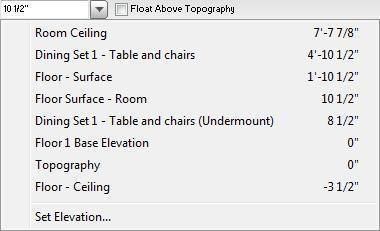
With the Elevation Bar, you can move selected items vertically by simply entering the elevation you want. This “on- the-fly” feature makes it a snap to make sure windows, doors, plants, and other elements, are in exactly the position you want. Additionally, the Elevation Bar automatically detects the elevation of nearby objects in the drawing. This allows you to precisely place a planter on top of a deck, for example.

The Set Elevation dialog box is available from the Edit menu when an object is selected. Additionally, the elevations of nearby objects in the drawing are automatically detected. This allows you to precisely place a planter on top of a deck, for example.
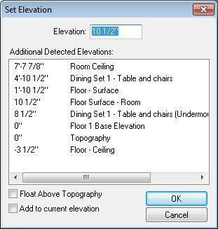
Note: To specify an amount in inches you may use either 18 or 18". To specify an amount in feet and inches they must be separated by a hyphen, for instance 18'-0", 8'-6", and so on. A single number like 20 will be understood as 20 inches.
To elevate an entity using the Elevation Bar 
- On the Edit Toolbar, click the Selection Tool and click to select the entity you want to elevate (hold down the SHIFT key as you click to select multiple entities). The Object Elevation field becomes active in the Elevation Bar.
Note: If an object in the selection set is configured to float above the topography, deselect the checkbox to elevate the object(s) freely.
- Type the elevation you want, in feet and inches, or just inches, then press ENTER. The selection is elevated based on the values you entered.
OR
Click the Object Elevation drop-down menu and select the surface to which you want the entity elevated. The object is elevated to the selected surface.
To elevate an entity using the Set Elevation dialog box
-
On the Edit Toolbar, click the Selection Tool and click to select the entity you want to elevate (hold down the SHIFT key as you click to select multiple entities).
-
Click Edit menu > Set Object Elevation. The Set Elevation dialog box is displayed.
-
Type the elevation you want in the corresponding field or select one of the available detected elevations and click OK.
Note: If an object in the selection set is configured to float above the topography, deselect the
checkbox to elevate the object(s) freely.
To make features follow custom topography
-
On the Edit Toolbar, click the Selection Tool and click to select the feature(s) you want to follow the custom topography.
-
In the Elevation Bar, select the Float Above Topography checkbox.

Float Above Topography Disabled Float Above Topography Enabled
To adjust entire floor elevation
-
Navigate to the floor you want to edit. For more information, see “Work on Floor”.
-
Click Edit menu > Adjust Entire Floor Elevation. The Adjust Floor Elevation dialog box is displayed.
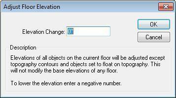
- Type the change in elevation you want applied to the current floor in the Elevation Change text box and then click OK (to increase the elevation type a positive number, to decrease the elevation type a negative number).
For example, if your floor is currently 8'-0" and you want to elevate the entire floor and its contents to 10'-0", type “2-0” to increase the floor two feet.
Copy to Floor
There may be times when you want multiple floors to contain duplicates. Copy to Floor leaves the entity in its original position and places a duplicate where you define. Move to Floor deletes these entities from their original position.
Note: To select more than one entity, press and hold SHIFT, while clicking.
To copy from one floor to another
- On the Edit Toolbar, click the Selection Tool and click to select the entities you want duplicated.
- Click Edit menu > Copy to Floor, then select the floor to which you want the selection(s) copied.

To move entities from one floor to another
- On the Edit Toolbar, click the Selection Tool and click to select the entities you want to move.
- Click Edit menu > Move to Floor, then select the floor to which you want the selection(s) moved.
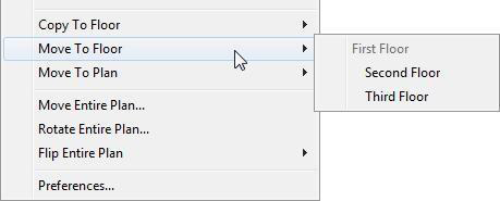
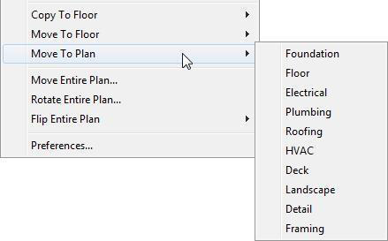
Move To Plan
With FloorPlan Software, you can move selections to different plan layers; Move to Floor deletes these entities from their original position. This will be useful if you want to move a feature between two stories that you have drawn.
To move features from one plan to another
-
On the Edit Toolbar, click the Selection Tool and click to select the feature you want moved. To select more than one entity, press SHIFT, while clicking entities.
-
Click Edit menu > Move to Plan, then specify the plan where you want the feature to appear.
(alternatively) Right-click the selection and click Move to Plan on the context menu that is displayed, then click which plan. The selection is moved to selected plan.
Note: Items on a hidden layer are not available during a Select All process and will not be moved along with the other items and features in your drawing.
Move Entire Plan
At any point during the design process, you can move the entire plan. With just a couple of mouse clicks, you can see how your dream home will look on different parts of your lot.
To move the entire floor plan
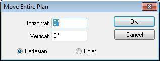
- Click Edit menu > Move Entire Plan. The Move Entire Plan dialog box is displayed.
-
Select either Cartesian or Polar, then type the amount you want the plan moved in the corresponding text boxes.
-
Click OK. The plan is moved based on the coordinates you specified.
Rotate Entire Plan
At any point during the design process, you can rotate the entire plan. With just a couple of mouse clicks, you can see how your dream home will look facing a different direction on your lot.
To rotate the entire floor plan
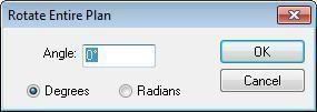
- Click Edit menu > Rotate Entire Plan. The Rotate Entire Plan dialog box is displayed.
-
Select either Degrees or Radians, then type the angle you want to rotate the plan in the Angle text box.
-
Click OK. The plan is rotated, based on the angle measurement you specified.
Flip Entire Plan
The Flip Plan function takes the existing plan orientation and reverses it, either horizontally or vertically.
To flip your drawing plan
- Click Edit menu > Flip Entire Plan and choose Horizontal or Vertical.