Before You Draw
To get the most benefit from FloorPlan Software, you should take a minute to become familiar with some of its basic concepts. With FloorPlan Software you can set a precise drawing scale, define units of measurement, and set the reference grid. There are also many performance settings you can apply to optimize drawing speed and 3D viewing.
Starting a New File
Starting a new file displays QuickStart, an easy way to start your design process. For more information, see “QuickStart”.
To save a new, unnamed file
-
Click File menu > Save As. The Save As dialog box is displayed.
-
Type a file name in the File Name text box and then click OK. Punch! Home Design Software automatically adds the PRO extension.
Opening a File
Opening a file makes it available for you to edit or print the plan. You can have more than one file open at a time. The exact number of files you can have open depends on the amount of memory in your system and the complexity of the home plan file. When you open a file, FloorPlan Software displays it in a new window.
To open an existing file
-
Click File menu > Open. The Open dialog box is displayed.
-
In the File Name box, type the name of the file you want to open, or search for the file by browsing folders or drives.
-
Select the file you want and click Open.
To see a list of recently opened files
- Click File menu > Open Recent and choose the file you want to open. The file loads into memory.
To clear the recently opened files listing
Click File menu > Open Recent > Clear Recent Designs List. A warning box is displayed. Click Yes to delete all files from the listing.
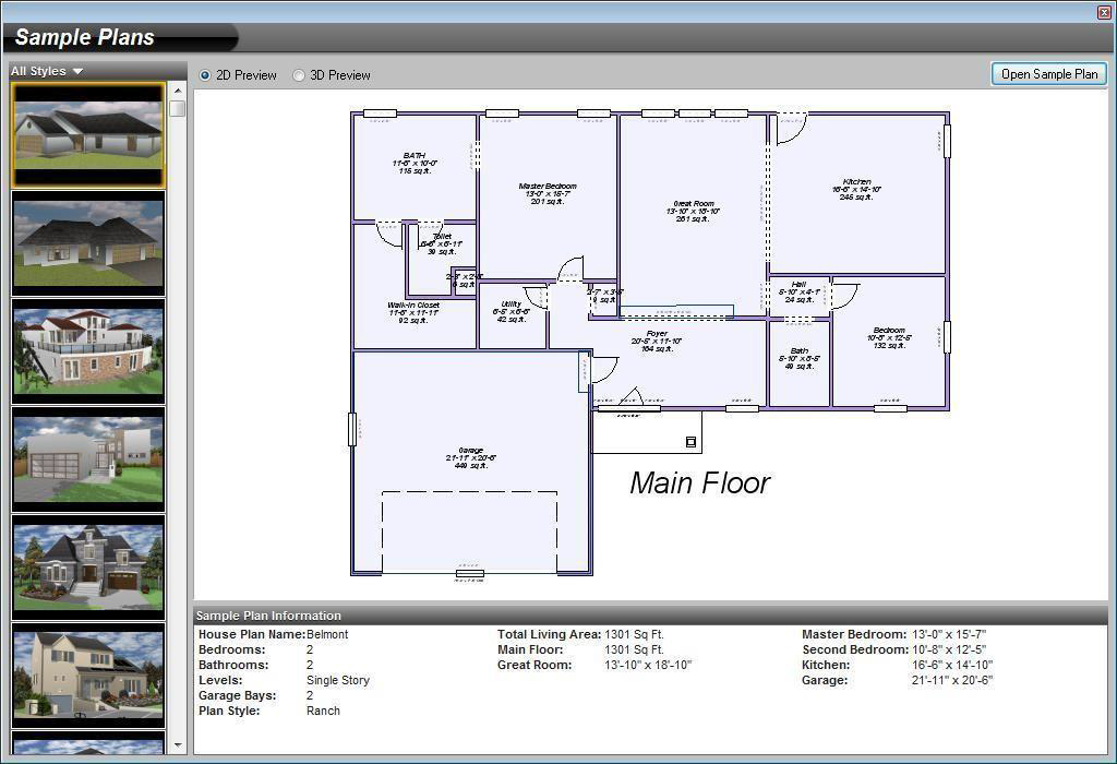
Accessing the Sample Plans
Sample plans are a set of pre-designed home plans, not created by an architect. They can be used as-is or can be edited to your liking. Each of the available sample plans include 2D and 3D previews, and room dimensions.
To open a sample plan
- Click File menu > Open Sample Plan.
(alternatively) Click Sample Plans on the Welcome window.
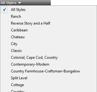
By default, all home styles are displayed. You can narrow the options by choosing the home style you want from the Style drop-down menu.
- Scroll through the style options and choose the one you want. A 2D preview is displayed, as well as the plan’s dimensions.
(optional) Click the 3D Preview radio button to see the home in 3D.
- When you find the plan you want, click Open Sample Plan. The plan is displayed in the design window.
Closing a File
When you finish working with a file, close it to remove the window from the screen and to free up your computer’s memory. When you are done working in FloorPlan Software, close all your files and exit the program.
To close a file
- Click File menu > Close. If you have unsaved changes in your plan drawing, FloorPlan Software prompts you to save them before it closes the file.
To close all open files and exit
- Click File menu > Exit. If any open drawings have unsaved changes, FloorPlan Software prompts you to save them before it closes their files.
Saving a File
When you open a file, FloorPlan Software copies the file to your computer’s memory. As you work, you modify the copy stored in memory. Any system failure or loss of power destroys that copy. To save your work permanently, you must save it to a file on a disc. A good rule of thumb is to save every 15 minutes or after you’ve completed any work you wouldn’t want to redo.
When you click the Save command, FloorPlan Software saves the active drawing, using the name and location you last gave it. You can create more than one version of a drawing or save copies on another disk for safekeeping. You can save each version under a different name or you can save them under the same name in different folders or on different disks.
To save an existing file
- Click File menu > Save.
(alternatively) Right-click and choose Save on the context menu that is displayed (or press CTRL+S).
To save a file to a different name, drive, or folder
-
Click File menu > Save As. The Save As dialog box is displayed.
-
If you want to save the drawing under another name, type a name in the File Name text box.
-
If you want to save the drawing to a different drive or folder, click a different drive and folder, or type the complete path in the File Name text box.
\4. Click OK.
Importing Files
You can import a variety of file types into FloorPlan Software. You can import the following types of files:
- 2D DXF/DWG file (described below)
- SketchUp file (described below)
- 3D Custom Workshop object
- 3DS File
- Material To Library
- Plant To Library
- 3D Background
To import a DXF/DWG file (2D only)
-
Click File menu > Import > DXF/DWG File. The Import DXF/DWG Design dialog box is displayed.
-
Find the file you want to import and then click to select it.
-
Click Open. The Import Scale dialog box is displayed. This determines the scale at which the file is imported.
Note: The import scale must match the scale units in the original plan.
- Choose a Scale from the drop-down menu and then click OK.
Note: Once you have imported your file, you will need to convert the lines and surfaces into Punch! intelligent features or intelligent elements before they can be viewed in 3D. For more information, see “Converting Details to Intelligent Elements”.
To import a SketchUp file
-
Click File menu > Import > SketchUp File. The Import SketchUp Design dialog box is displayed.
-
Find the file you want to import and then click to select it.
-
Click Open. The object is placed in the center of your 2D design. The Status Bar displays the progress, as the file is converted.
You can edit the size and render options on the Properties tab after the file is imported.
Exporting Files
You can export a 2D drawing file or a rendered image of your 3D View window to BMP, JPG, PNG, or TIFF format. Images can be exported in Textured, Wireframe, or ClearView modes. The exported image appears just as your 3D View window does. For best results, adjust your rendering settings to a high-resolution before exporting. Size is also controlled by how your 3D View window appears; the larger the 3D View window, the larger the file will be. For more information on controlling the 3D View environment, see “Viewing in 2D & 3D”.
You can also export an animation (see “To export animation”) and a landscape quote (see “Exporting a Landscape Quote”), if your file includes these features.
You can even send a list of plants and mulch beds to your iPhone and load it into the Landscape Quote app. Then you can enter the prices from the nursery to keep track of costs.
Exporting a DXF or DWG File
You can export 2D floor plan files using a DXF or DWG file format so they are compatible with another CAD system.
- Format drop-down menu allows you to choose either a DXF or DWG file format.
- Version drop-down menu allows you to choose which version of the file format you want to export.
- Color checkbox allows you to maintain the plan colors that are associated with the components on different plan tabs. When deselected, the entire drawing is exported in a monochromatic color scheme for all of the components.
To export a DXF/DWG file
-
Click File menu > Export > DXF/DWG File. The Export Options dialog box is displayed.
-
Choose the Format and Version you want.
(optional) Select the Fills / Patterns checkbox to export fills and patterns.
-
Click Export. The Export dialog box is displayed.
-
Choose a destination for the file then type a file name in the File Name text box.
-
Click Save. Punch! Home Design Software automatically adds the DXF or DWG extension.
Exporting a 2D Image
You can export your 2D drawing as an image file. There are many options available for exporting a 2D image.
- Export Format specifies the file format for the 2D image.
- Keep image size proportional checkbox allows you to resize the image so the width and height are the same as the largest direction. When deselected, the original image size is maintained.
- Crop at lot boundary checkbox crops the image where the lot ends
- When selected. When deselected, the image extends past the lot boundary.
- Image Size slider controls the size of the image to be exported.
- Print current view only checkbox limits the exported image to what is visible in the current 2D view.
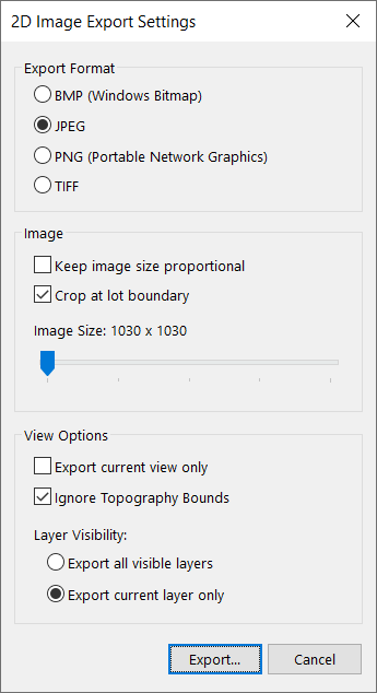
- Ignore Topography Bounds checkbox controls if the topography line boundaries are considered in the exported image. When selected, the image is cropped to include the home design; when deselected the image fits the home design and the length of each topography line. If you do not need to see the full length of all of the topography lines select this option.
- Layer Visibility allows you to choose to export all of the visible layers on the current plan or just the current plan layer.
To export a 2D image
-
Click File menu > Export > 2D Image. The 2D Image Export Settings dialog box is displayed.
-
Choose settings you want under Export Format, Image, and View Options, and then click
Export. The Export Image dialog box is displayed.
-
Choose a destination for the file then type a file name in the File Name text box.
-
Click Save. The 2D image is exported to the location you’ve specified. Punch! Home Design Software automatically adds the extension.
Exporting a 3D Image
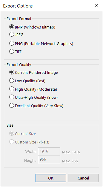
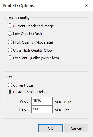
You can export your rendered 3D view as an image file. There are many options available for exporting a 3D image.
\1. Export Format specifies the file format for the 3D image.
\2. Export Quality specifies the render quality for the 3D image.
\3. Size options allow you to export the image using the current 3D view size or choose a custom width and height.
To export a 3D Image
-
Click File menu > Export > 3D View Image. The Export Options dialog box is displayed.
-
Choose settings you want under Export Format, Export Quality, and Size, and then click OK. The Export Image dialog box is displayed.
-
Choose a destination for the file then type a file name in the File Name text box.
-
Click Save. The 3D image is exported to the location you’ve specified. Punch! Home Design Software automatically adds the extension.
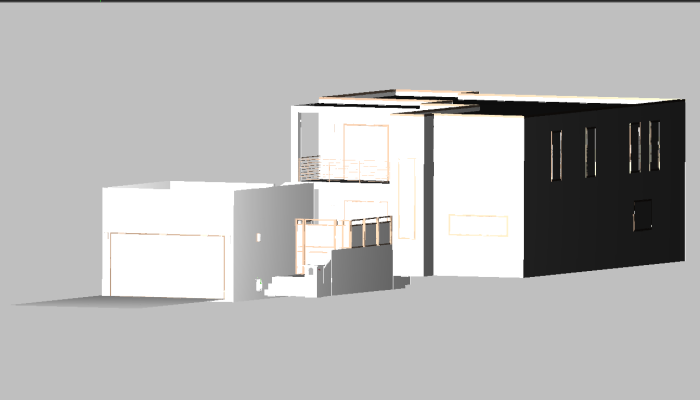
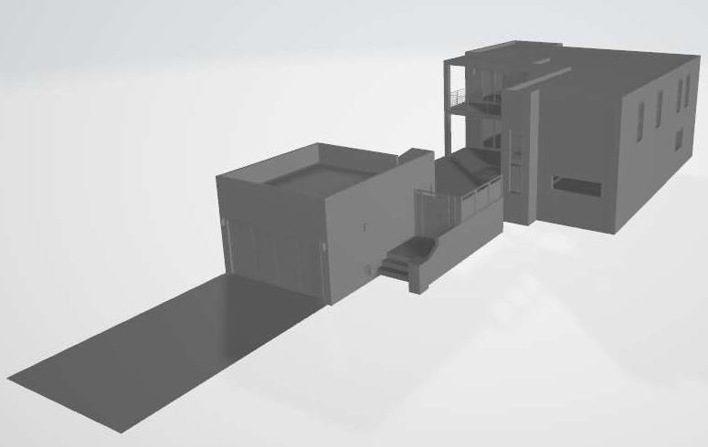
Exporting 3D Files
The FloorPlan Models can be exported to 3D files for use with other programs as well as 3D printing (for some formats). Textures and topography / landscape elements are not exported.
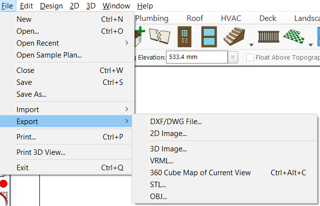
Exporting a VRML File
You can export a 3D model to a VRML file mainly for use in 3D modeling with other programs.
To export a VRML file
-
Click File menu > Export > VRML. The Export VRML dialog box is displayed.
-
Choose a destination for the file then type a file name in the File Name text box.
-
Click Save. The VRML file is exported to the location you’ve specified. Punch! Home Design Software automatically adds the WRL extension.
-
Note that the files are exported without textures.
Exporting a STL File
You can export a 3D model to a STL file. This format is used to create a solid object from the Punch! 3D model.
To export an STL file
-
Click File menu > Export > STL. The Export STL dialog box is displayed.
-
Choose a destination for the file then type a file name in the File Name text box.
-
Click Save. The STL file is exported to the location you’ve specified. Punch! Home Design Software automatically adds the STL extension.
\4. Note that the files are exported without textures.
Exporting an OBJ File
You can export a 3D model to an OBJ file mainly for use in 3D modeling with other programs as well as 3D printing.
To export an OBJ file
-
Click File menu > Export > OBJ. The Export OBJ dialog box is displayed.
-
Choose a destination for the file then type a file name in the File Name text box.
-
Click Save. The OBJ file is exported to the location you’ve specified. Punch! Home Design Software automatically adds the OBJ extension.
Note Export to the OBJ format includes Textures used in the Punch! drawing
Exporting a 360 Cube Map of Current View
This feature allows you to create a 360° Cube Map of your current view, that can be visualized and shared online via the Punch! Online Viewer.
To export a 360 Cube Map
- In Liveview walkthrough, visualize the room or view that you wish to export. Confirm that you are in the center of the room.
Click File menu > Export > 360 Cube Map of Current View or use Ctrl+Alt+C. > The Export CubeMap dialog box is displayed.
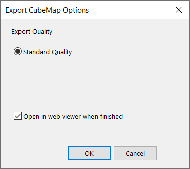
- Standard Quality is the Render Quality and select Open in web viewer when finished to open the Cube Map immediately.
3. Choose a destination for the file then type a file name in the File Name text box.
- Click Save. The Cube Map is exported to the location you’ve specified. FloorPlan Software automatically adds the BMP extension.
5. A browser showing the viewer will open (if you selected this option).
Alternatively, you can open a browser > go to http://viewer.punchsoftware.com and open you file by clicking on the open file field.

Look for the file in your computer in the location you’ve specified.
Once you open the file, you will be able to use the commands on the left bottom side and have a 360° view of the room.
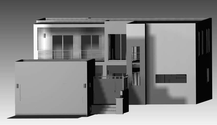
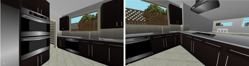
Images Exported using Standard Quality
Printing Floor Plans
FloorPlan Software prints, using the current Windows printer drivers. You can, however, print using any installed printer. Using the Print Setup dialog box, you can specify a printer from those currently installed. You can print your drawing in color or in black and white; it can be printed to scale or you can print it all on one page, depending on your needs. Follow these steps to print your 2D drawing.
Note: Gridlines will print if they are visible when the drawing is printed.
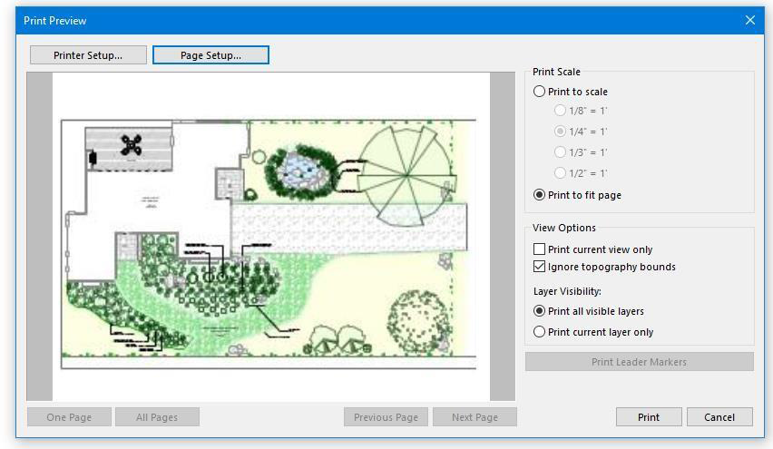
Print Scale options allow you to print to a specified scale or fit the drawing to the page.
- Print current view only checkbox limits the printout to what is visible in the current 2D view.
- Ignore Topography Bounds checkbox controls if the topography line boundaries are considered in the exported image. When selected, the image is cropped to include the home design; when deselected the image fits the home design and the length of each topography line. If you do not need to see the full length of all of the topography lines select this option.
- Layer Visibility allows you to choose to print all of the visible layers on the current plan or just the current plan layer.
- Print Leader Markers button allows you to print just the leader dimensions in your drawing that use the Marker type.
To print a floor plan
-
Click File menu > Print (or press CTRL+P). The Print Preview dialog box is displayed.
-
Choose the Print Scale options and View Options you want and then click Print. The drawing is printed based on your current settings.
To change printer / page settings
-
Click File menu > Print (or press CTRL+P). The Print Preview dialog box is displayed.
-
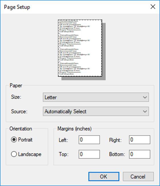
Click the Printer Setup button, in the top left corner. The Print Setup window is displayed.
-
Choose the printer you want to use.
(optional) Change the paper orientation and size.
- Click OK and then click Print.
Printing a 3D View Rendering
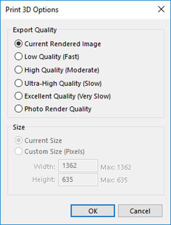
FloorPlan Software streamlines the process used to print the 3D View images. With just a couple of clicks, you can print beautiful, full-color renderings of your design.
- Export Quality specifies the render quality for the 3D view printout.
- Size options allow you to print the image using the current 3D view size or choose a custom width and height.
To print a 3D View rendering
-
Click File menu > Print 3D View. The Print 3D Options dialog box is displayed.
-
Choose the Export Quality and Size options you want.
-
Click OK. The Print dialog box is displayed.
-
Choose the printer you want to use.
(optional) Change the paper orientation and size.
\5. Click OK.
Printing an Elevation View
You can print the current elevation view to create a fully rendered printout of the view.
- Print Quality specifies the render quality for the 3D view printout.
- Print Options allow you to print the image to fit the printed page or using the plan scale that is specified.
To print a 3D Elevation View rendering
-
Open the Elevation View and set the view of your design that you want to print.
-
Click File menu > Print 3D View. The Print Elevation Options dialog box is displayed.
-
Choose the Print Quality and Print Options you want.
-
Click OK. The Print dialog box is displayed.
-
Choose the printer you want to use.
(optional) Change the paper orientation and size.
\6. Click OK.
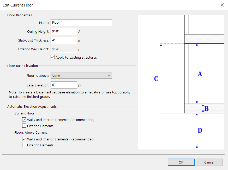
Working with Floors
Floors are designated levels upon which your structure is built. Your design may use only one floor or up to 20 (depending on your software version). Floors are not necessarily placed one on top of another; floors may also exist at the same elevation but independent of each other.
By default, a project includes three floors:
- Floor 1 is the base level floor
- Floor 2 is above Floor 1
- Floor 3 is above Floor 2
When a floor is positioned above another floor, an association is established so changes to the underlying floor are reflected in the above floors. For example, if Floor 2 is above Floor 1, and the ceiling height of Floor 1 is changed from 8'-0" to 10'-0", the base elevation of Floor 2 is also updated to include the additional two feet.
Additionally, walls and interior elements that exist on the current floor and above floors can be updated to reflect changes to the floor properties.