3D Custom Workshop makes it extremely easy to change objects once they are drawn. In this section, you will find instructions on techniques that make rotating, resizing, and other edits very simple.
You will also learn how to use layers, lock and unlock; in addition, you’ll learn to create groups that will make complex objects much more manageable. The flip and mirror techniques are also described and are useful when you need perfectly symmetrical objects.
Controlling Selection Mode
Object Selection Mode is active by default. Object selection, along with point selection, controls how your edits impact your object.
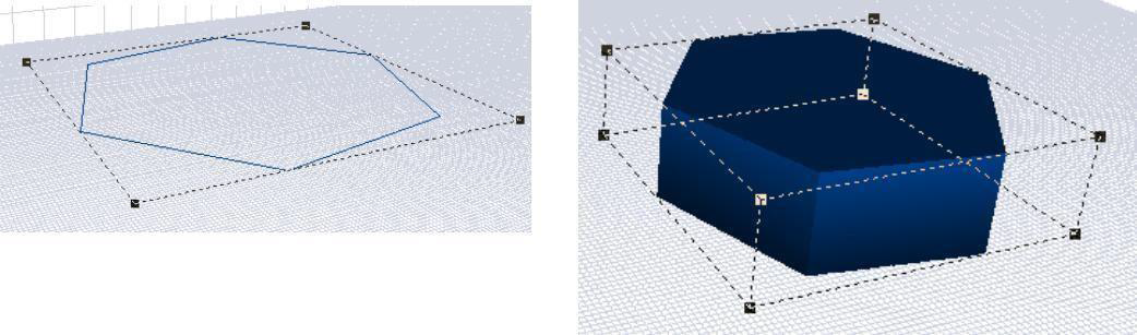
 Object Selection Mode
In object selection mode, changes affect the object as a whole. This is ideal for moving a selection, or group of selections.
To use object selection mode 
- Click the button at the bottom of the design window so Object Selection icon is displayed. (alternatively) Click Options menu > Object Selection.
Note: To restore colors and materials, click the Rendering Style toggle at the lower left of your window, or on the View menu, click 3D Rendering Style, then click Textured.
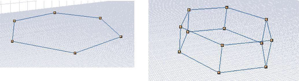
 Point Selection Mode
In point selection mode, each vertex of the object is treated separately, so you are able to move each vertex or point individually in your drawing. This is ideal for detailed edits.
You can change the color of the point handles to make them most distinguishable or blend in, depending on your needs. For more information, see “Controlling Default Colors”.
To use point selection mode 
- Click the button at the bottom of the design window so Point Selection icon is displayed. (alternatively) Click Options menu > Point Selection.
Note: To restore colors and materials, click the Rendering Style toggle at the lower left of your window, or on the View menu, click 3D Rendering Style, then click Textured.
To select all points
- Right-click an object and choose Select All Points from the context menu.
To select all points on a segment
- Right-click a line segment where you want to select all points and chose Select Segment from the context menu. All the points along that segment are selected.
OR
- Right-click a point where you want to select all points of the segment and choose Select Segment Points from the context menu. All the points along that segment are selected.
To select all points along an extrusion path
- Right-click a point and choose Select Extrude Points from the context menu. All of the points along the extrusion path are selected.
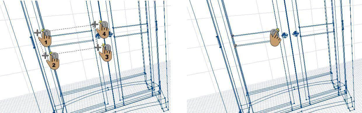
Selecting Points within an Object
The Select In Polygon Tool is a versatile tool that allows you to select objects or points that lie within another object. This tool allows you to click points to define a selection area, much like drawing a polygon shape.
To select points within an object 
-
Enable Points Selection mode. For more information, see “Point Selection Mode”.
-
Click the Select In Polygon Tool.
-
In the design window, click to set the start point and drag to define the shape of the polygon.
-
Continue to click points and drag to define the selection shape around the points or objects you want selected, and then right-click to select points.
Adding and Removing Points
You can adjust a shape and gain more control over its appearance by adding or removing points to 2D shapes.
To add and remove points, you must be in Point Selection mode. For more information on selections modes, see “Controlling Selection Mode”.
To add a point to an object
- Right-click the segment where you want to add a point and choose Add Point on the context menu. A point is added to the object where your cursor was positioned.

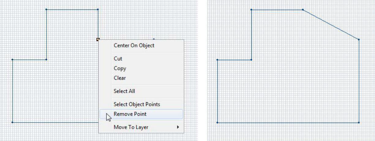
To remove a point from an object
- Right-click the segment where you want to remove a point and choose Remove Point on the context menu. The point is removed from the object.
Changing Curve Tension
To further control the look of the shapes drawn with any of the arc or curve tools, you have control over the degree of curve assigned to them. Curve Tension is measured between 1 and 50. Specifying 1 in the dialog box results in very little tension being applied, while specifying 50 is the maximum amount allowed and causes a greatly- exaggerated curve.
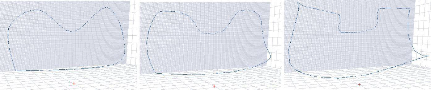
Curve Tension=5 Curve Tension=10 Curve Tension=20
To change curve tension
- Click to select an object and then click the Adjust Curve button on the Properties Bar. The Curve Tension dialog box is displayed.
(alternatively) Click Options menu > Curve Smoothing > Curve Tension.
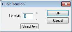
- Type the amount of tension that you want or click the arrows to increase or decrease the value incrementally, and then click OK. The Curve Tension you specified is applied.
To control default curve-drawing smoothness 
-
Click the Custom Options button. The Custom Options dialog box is displayed. (alternatively) Click Options menu > Custom Options.
-
Drag the 2D Curve-Drawing Smoothness slider to decrease or increase the drawing smoothness and then click OK.
Note: When changed, the drawing smoothness affects all curves in the drawing.
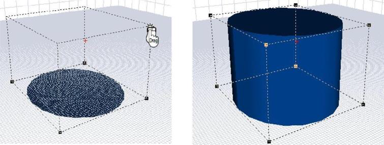
Extruding a 2D Object
Once you draw an object in 2D you can add a third dimension at any time. The Extrude Tool makes this a straight- forward process, by simply clicking and dragging to the desired dimension. To extrude an object with more precision, you can use the Extrude dialog box to define the segment spacing, and how many segments to which you want to extrude.
To manually extrude a 2D object 
- Click to select the object to be extruded and, on the Standard Toolbar, click the
Extrude Tool.
-
Click-and-drag in the direction that you want the object to extrude. Dimensions appear in the Readout Bar as you extrude.
-
Release the mouse button to end extrusion mode.
Note: Using the Extrude Tool always extrudes the selection perpendicular to the active grid.
To extrude an object by a specified amount
-
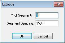
Click to select the object to be extruded and then click Edit menu > Extrude. The Extrude dialog box is displayed.
-
of Segments defines number of segments want in the extruded shape.
- Segment Spacing defines the length of each segment in the extruded shape.
Note: Specifying an extrusion value using the Extrude dialog box always extrudes the selection perpendicular to the grid on which it was drawn.
2. Specify the extrude settings you want and click OK.
Revolving a 2D Shape
Another way to add a third dimension is by using the Revolve command. This command is useful when creating table legs, lamps, vases, and so on. Radians and degrees are two ways of measuring circular distances. One radian equals 180-degrees.
Note: Objects revolve in the direction of the active drawing grid.
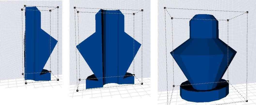
90-degrees 180-degrees 360-degrees
To revolve a 2D object
- Click to select the object to be revolved and then click Edit menu > Revolve. The Revolve dialog box is displayed.
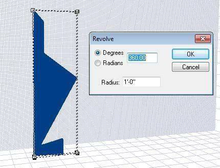
-
Choose Degrees or Radians and type the measurement you want in the corresponding text box. Measurements are from -360 to 360-degrees or -6.28 to 6.28 radians.
-
Radius defines the size of the circle the shape revolves around. This is measured in the scale you have defined.
-
Specify the revolve settings you want and click OK.
Applying Skew
To skew an object means to slant it along a selected axis. This is a useful tool for adding beveled edges to counters, diagonal legs to tables, and so on. You can use the Skew Tool to manually drag points to define the skew or specify values for a more precise slant.
Note: Objects are skewed in the direction of the active drawing grid.
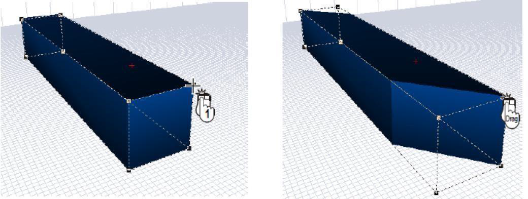
To skew an object freely 
-
Click to select the object you want to skew and then click the Skew Tool.
-
Click a corner point of the object and drag in the direction you want the object to be slanted. Dimensions appear in the position readout bar as you draw.
-
Release the mouse to stop skewing the object.
To skew an object a specified amount
- Click the object to skew and then double-click the Skew Tool. The Skew dialog box is displayed.
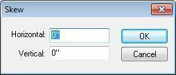
- Horizontal defines the difference in distance between horizontal points
- Vertical defines the difference in distance between the vertical points.
Note: The higher the value the more intense the skew.
- Type the Horizontal and Vertical values to which you want the object skewed and then click OK.
Rotating an Object
With the Rotate Tool you can easily spin an object around any point on any drawing grid. This is useful when you want to face an object in a different direction from which it was drawn. You can use the Rotate Tool to manually drag points to define the angle or specify a precise rotation angle.
Note: Objects are rotated based on the active drawing grid.
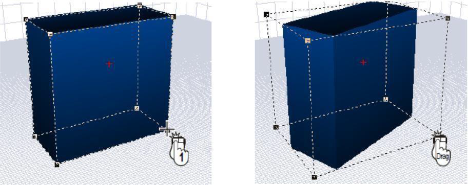
To rotate an object freely 
-
Click to select the object to rotate and then click the Rotate Tool.
-
Click a corner point of the object and drag in the direction that you want to rotate.
-
Release the mouse to stop rotating the object.
To rotate an object a specified amount
- Click to select the object to rotate and then or double-click the Rotate Tool. The Rotate dialog box is displayed.
(alternatively) Click Edit menu > Rotate.
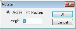
-
You can rotate a selection using Degrees or Radians. Click the radio button corresponding to the system you want to use.
-
Type the angle you want to rotate the selection in the Angle text box and click OK.
To rotate an object in 1-degree increments
-
Click to select the object to rotate. Selection handles appear around the object.
-
Press SHIFT, then press the left or right arrow key to rotate the selection in that direction.
Elevation Slider
With the Elevation Slider, objects can easily be moved vertically, regardless of which grid is active at the time. The Elevation Slider will display in the unit of measure specified in the home design program; for example, measurements will be displayed in metric automatically, if you are designing in your home design program, using metric measurements.
For more information, see “Elevation Slider”.
Specifying Object Size
With the object size option, you can specify exact measurements for each object, either as a percentage of the original size or by specifying dimensions in inches. This is very useful, especially when you know how large or small an object must be to fit a specific space in your home.
To change an object’s size
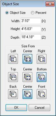
- Double-click the object you want to resize. The Object Size dialog box is displayed.
(alternatively) Click to select the object and click the Resize Object(s) button on the Properties Bar (or click Options menu > Object Size).
Object Size lets you resize using measurements.
Percentage lets you resize using a percentage of the original size. Size From options let you choose the direction the selection is resized from.
-
Choose the resize method and type the values you want in the corresponding text boxes.
-
Choose the Size From direction you want and then click OK. The object is resized to the exact measurements or percentage you specified.Grouping Objects
By defining a Group, you create a set of selected objects that are then treated as one item. You can have unlimited groups in a drawing.
To control object groups
-
Press and hold SHIFT and then click each object that you want to be included in the group.
-
On the Control toolbar, click the Group Tool. The selections are grouped as one object. Click the Ungroup Tool to ungroup a set of objects.
(alternatively) Click Edit menu > Group or Ungroup.
Locking Objects in Place

Many times, you will want to lock an object in place after it is positioned. This avoids accidentally moving the object.
To control object locks
- Click to select the object you want to edit.
(optional) Hold down SHIFT and click to select multiple objects.
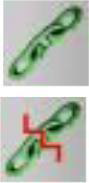
- On the Control toolbar, click the Lock Tool to lock the selection(s) in place. Click the Unlock Tool to unlock the selection(s). (alternatively) Click Edit menu > Lock or Unlock.
Hiding Detection
When you are working in layers, it will be helpful to make some objects unable to be selected, which makes it easier to select objects underneath. The Hide Detection feature makes this a simple process.
To the hide detection of an object 
-
Click to select the object you want to hide from detection. (optional) Hold down SHIFT and click to select multiple objects.
-
On the Control toolbar, click the Hide Detection Tool. (alternatively) Click Edit menu > Hide Detection.
To detect objects 
- On the Control toolbar click the Detect Tool and then click to select the object. (alternatively) Click Edit menu > Detect All.
Working in Layers
Using the Layer option, you can store different information on different layers of your drawing. The Active Layer’s name is always displayed on the Design toolbar.
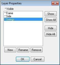
From the Layers tab, you can choose to show or hide certain layers, which makes viewing and working on individual layers easy and uncluttered. Many of the functions are available through the Layer Properties dialog box. When making changes in the Layer Properties dialog box, you must click OK before your changes take effect.
To make complex objects more manageable, break them into logical layers. If you are drawing a chair, for example, you may want a separate layer for the back, the legs, the cushion, and so on.
Most of the layer management tasks can be performed on the Layers tab or using another method, so alternate methods are included where possible. These types of tasks include creating and deleting layers, controlling layer visibility, and more.
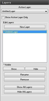
- Active Layer drop-down menu allows you to choose which layer is your current working layer. Select the Show Active Layer Only checkbox to hide all layers except the Active Layer.
(alternatively) Click Design menu > Active Layer then choose your active layer from the submenu.
- Show All Layers button displays all of the objects on all of the layers in the workspace.
(alternatively) Click Design menu > Visible Layers > Show All Layers.
- Hide All Layers button hides all of the objects on all of the layers from the workspace.
(alternatively) Click Design menu > Visible Layers > Hide All Layers.
- New button opens the New Layer dialog box where you can define a new layer. Type a name for the layer and click OK.
(alternatively) Click Design menu > Layer Properties and then click the New button.
- Show button allows you to show a hidden layer. Select the layer you want to see and click the Show button to display it in the workspace.
(alternatively) Click Design menu > Layer Properties then select the layer and click the Show button.
- Hide button allows you to hide a visible layer. Select the layer you want to hide and click the Hide button to remove it from the workspace.
(alternatively) Click Design menu > Layer Properties then select the layer and click the Hide button.
- Rename button opens the Rename Layer dialog box where you can change the name of an existing layer without affecting the objects on the layer. Type a new name for the layer and click OK.
(alternatively) Click Design menu > Layer Properties then select the layer and click the Rename button.
- Remove button deletes a layer and its contents from your design.
(alternatively) Click Design menu > Layer Properties then select the layer and click the Remove button.
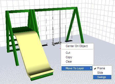
To move a part of the drawing to a new layer
- Select the object you want to move to another layer then click the Move To Layer button on the Properties Bar and choose the layer. The selection is moved to the new layer.
(alternatively) Right-click the part of the drawing you want to move to another layer, then click
Move to Layer on the context menu that is displayed, then choose the layer.
Moving an Object
You can move an object easily, using the click and drag method or by specifying coordinates.
Note: Objects are moved based on the active drawing grid.
To move by dragging
- Click to select the object you want to move and then click-and-drag the object to where you want it displayed.
To move by specifying the distance
-
Click to select the object you want to move.
-
On the Properties tab, type the distance you want the object moved in the corresponding text boxes. Press ENTER to accept each new value.
To align object faces
-
Hold down the SHIFT key and click to select the objects you want to align.
-
Click Edit menu > Align Objects and choose the face by which you want the selections aligned. The objects are aligned based on the component you selected.
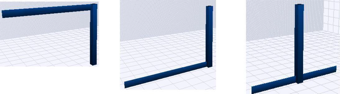
Align Object Top Align Object Bottom Align Object Vertical Center
Using Flip
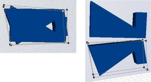
The Flip function takes the original object and reverses it either horizontally or vertically. Depending on which grid is active, flipping an object varies.
Flip Horizontal
When you flip an object horizontally, the points along the horizontal edge are flipped, based on the active drawing grid.
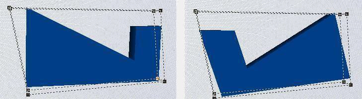
Original Flipped
To flip an object horizontally 
- Click to select the object you want to flip and then, on the Control toolbar, click the
Flip Horizontal Tool.
(alternatively) Click Edit menu > Flip > Horizontal.
Flip Vertical
When you flip an object vertically, the points along the vertical edge are flipped, based on the active drawing grid.
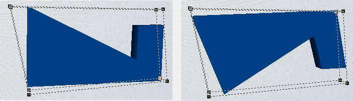
Original Flipped
To flip an object vertically 
- Click to select the object you want to flip and, on the Control toolbar, click the Flip Vertical Tool.
(alternatively) Click Edit menu > Flip > Vertical.
Using Mirror
Mirror works much like the Flip function. The difference is that mirror leaves the original and makes a duplicate. Mirror creates two identical objects that face one another. Depending on which grid is active, mirroring an object varies.
Mirror Horizontal
When you mirror an object horizontally, a mirror copy is created along the horizontal edge, based on the active drawing grid.
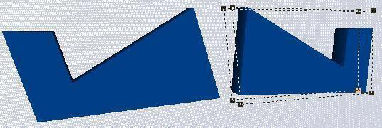
Original Mirrored
To mirror an object horizontally 
-
Click to select the object you want to mirror and, on the Control toolbar, click the Mirror Horizontal Tool. A mirror copy of the object is created. (alternatively) Click Edit menu > Mirror > Horizontal.
-
Drag the mirrored copy into position as needed.
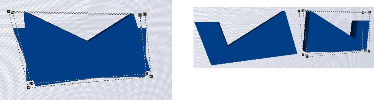
Mirror Vertically
When you mirror an object vertically, a mirror copy is created along the vertical edge, based on the active drawing grid.
To mirror an object vertically 
-
Click to select the object you want to mirror and, on the Control toolbar, click the Mirror Vertical Tool. A mirror copy of the object is created. (alternatively) Click Edit menu > Mirror > Vertical.
-
Drag the mirrored copy into position as needed.
Duplicating Objects
Similar to standard copy/paste functionality, the duplicate feature creates an exact copy of the object you select. In the duplicate properties dialog box, you can specify the number and specific offset of a series of duplicates. You can create duplicates using the default properties or adjust the properties before creating duplicates.
Note: Objects are duplicated based on the active drawing grid.
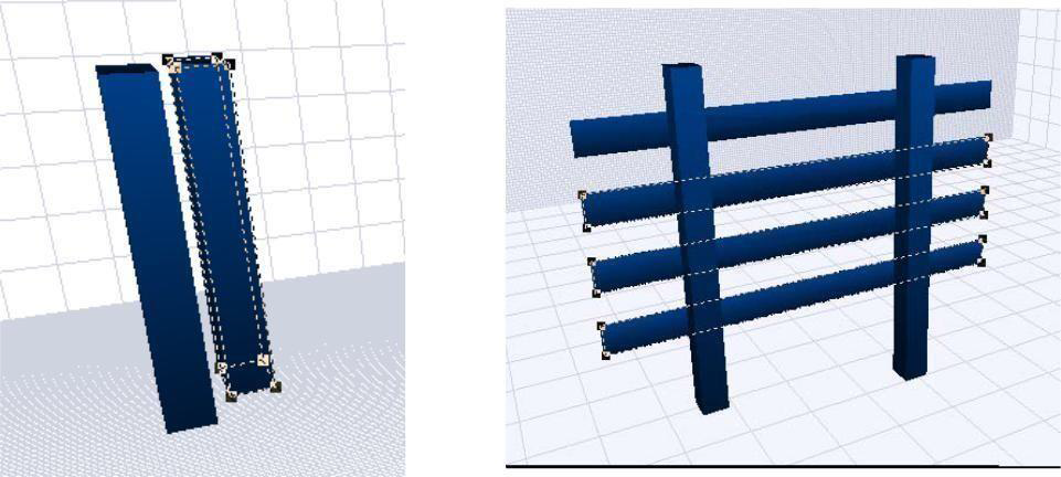
Duplicate (on right) Series of vertical duplicates
To create a duplicate 
- Click the object you want to duplicate and, on the Control toolbar, click the Duplicate Tool. The Duplicate Properties dialog box is displayed.
(alternatively) Click Edit menu > Duplicate > Duplicate Properties.
(optional) Click Edit menu > Duplicate > Duplicate Object to automatically create a duplicate based on the default duplicate properties.
-
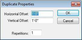
The Offset values specify the distance between duplicates. Type the distance each duplicate object should be offset, horizontally and vertically, from the original object and from each other (these can be negative values).
-
Repetitions defines the number of duplicates. Each duplicate is positioned based on the Offset values.
-
Specify the duplicate properties and then click OK. The object is duplicated at the offset(s) you defined.
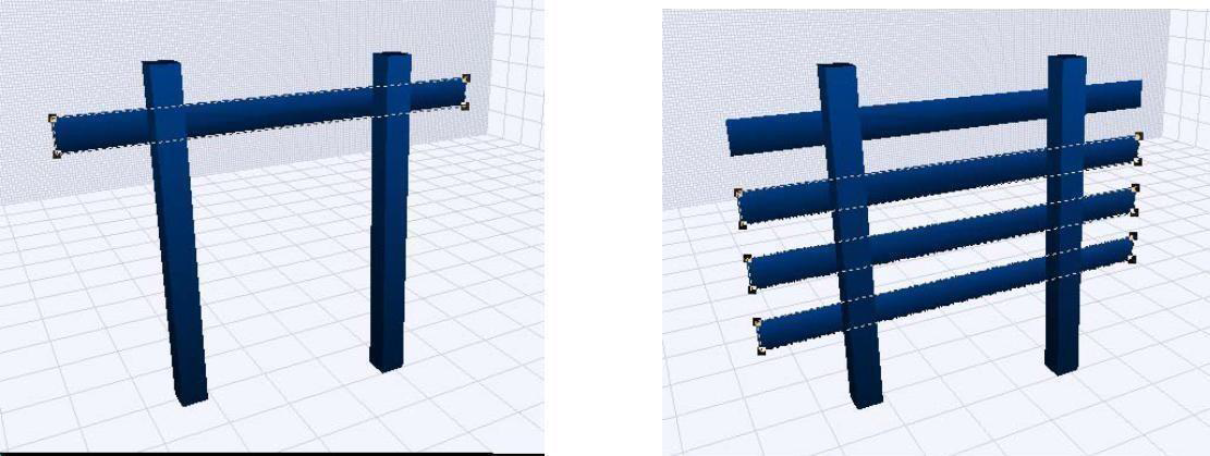
Above, the Horizontal Offset is 0, the Vertical Offset is -1'-0", and the Repetitions value is 3.