Drawing in 2D
This Software provides many options for looking at your design onscreen. You can display several windows, each containing a different view of your plan. This gives you the flexibility to view your drawing as a 2D plan, as a 2D plan with a corresponding 3D view or using only Punch! 3D View.
When viewing your 2D home plan, you can magnify the view by zooming in, reduce the view by zooming out, or pan the view in any direction.
3D viewing provides many options, from walking through the home plan to flying around the plan or viewing the framing or completion phase of your project. You can adjust 3D display settings using a variety of viewing features, including adding shadows, for a realistic effect, or adjusting the lighting intensity of the view. Finally, you can create a photo-realistic view of your design.
2D Drawing Methods
There are some common 2D drawing methods that you’ll use repeatedly while creating your design in Punch! Below are detailed steps for each of the drawing methods. Practice these methods before you begin, or refer back to this information as you draw. If a tool requires a different drawing method, it is explained where the tool is described.
Keyboard Shortcut Quick Reference
here are a couple of helpful keyboard shortcuts to be aware of as you draw. These can be helpful with precisely drawing segments.
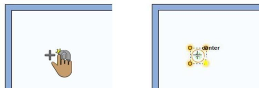
Click Once to Place
This method is used for items that do not attach to walls, like columns, floor and ceiling receptacles, fixture lights, furnaces, and other items that are positioned freely in a design.
To draw using Click Once to Place
- Position your cursor where you want the selection to be placed and click your left mouse button. The selection is placed at the location you click.
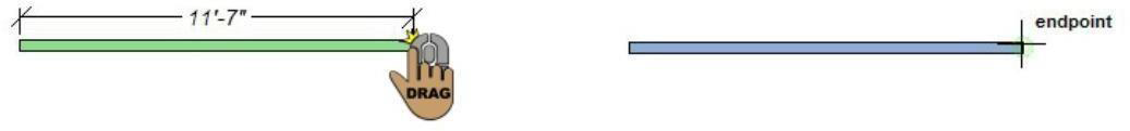
Click-and-Drag
This method is used for items like walls, roofs, pre-defined shapes (rectangle, circle/oval, line, arc, multigon), and other shapes that are based on a user-defined size. For details on controlling the automatic dimensions display.
To draw using Click-and-Drag
- Position the cursor at the start point for the shape, then hold down the left mouse button and drag from the start point to the desired length. A rubber band line is displayed as you drag. Release to place.
Define 2D Shape
This method is used for manually drawn shapes like floors, decks, railings, and more. Below is an example of the Draw Method drop-down menu for the Floor Tool (available on the Floor plan tab). Each Draw Method describes how the shape is drawn.
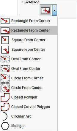
To draw using Define 2D Shape
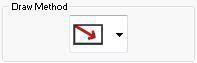
- When a tool that uses Define 2D Shape is active, the Draw Method drop-down menu becomes available on the Properties tab.
- Click the Draw Method drop-down menu and choose the shape and method you want for the active tool.
- Draw the shape based on the method you chose. For detailed steps to draw shapes, see the following sections:
- “Drawing Rectangles and Squares”
- “Drawing Circles and Ovals”
- “Drawing Lines”
- “Drawing Polygons”
- “Drawing Arcs”
- “Drawing Circular Arcs”
- “Drawing Multigons”
- “Drawing Curves”
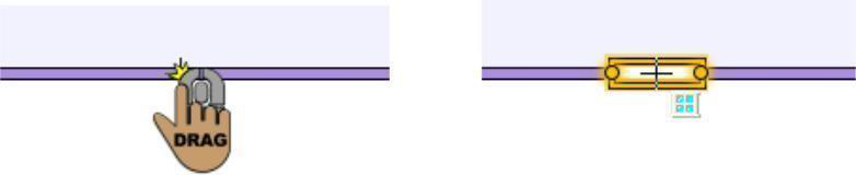
Drag Along Wall
This method is used for wall attachments such as windows, doors, receptacles, and more. As wall attachments, objects remain attached to the wall even if the wall is moved.
To draw using Drag Along Wall
- Click-and-drag along a wall, release to place on the side where you want it.
2D Editing Methods
There are some common editing methods that you’ll use repeatedly while creating your design in Punch! Below are detailed steps for each of the editing methods. Practice these methods before you begin, or refer back to this information as you draw. If a tool requires a different drawing method, it is explained where the tool is described.
For additional editing techniques, see the chapter titled “Edit Your Design”
Selecting Points and 2D Shapes
You can select an individual point or segment on a shape or the entire shape.
To select points
- On the Edit Toolbar, click the Selection Tool.
- Hold down the SHIFT key and click to select one point or segment
To select a 2D shape
- Click the Selection Tool and then double-click a point or segment in a 2D shape to select the entire shape.
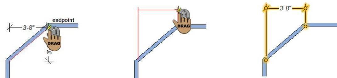
Reshaping and Resizing 2D Objects
Objects created using the Click and Drag or Define 2D Shape drawing method can be reshaped or resized by dragging a point or segment.
To reshape and resize 2D objects
- Click the Selection Tool and then click to select the point or segment you want to edit.
- Drag the selection to reshape or resize the object. Release to place.
Elevating Objects
You can adjust the elevation of an individual object or a group of objects to a specific value or to match the elevation of a nearby object. You can also elevate all of the objects on an entire floor. For more information, see “Elevating Objects”.
Component Description
Components that are added to your design from one of the plan tabs have a default description you can change. The description text is used in the Description column in Estimator. In the example below, the Sink Description is displayed for editing.

Updates to the description text only affect the component in your plan; changes do not affect the original item in the content library. To edit the component description information in the library, copy the item to the User Library and then edit its details.
You can also edit the object information for custom workshop objects.
To edit component description
- Click the Selection Tool and then right-click the object and choose Description from the context menu.
- Edit the text as needed and click OK.
Using the Grid
With This Software you can set specific grid properties that aid in drawing your home plan. You can set points, based on the reference grid, which is useful when you want to make sure certain points are specified precisely.
Grid settings have a direct impact on the ease of aligning objects and snapping objects to the grid. When using the Snap to Grid feature, items that are dragged and dropped on the design window are automatically snapped, or placed, to align with the current grid. By default, Snap to Grid is on.
You can customize grid settings by selecting grid spacing, grid style, and hiding or displaying minor grid lines.
To display the grid
- Click 2D menu > Grid Visible. The grid is displayed on the design window.
(alternatively) Right-click the design window and click Grid Visible on the context menu that is displayed.
To align objects/features with an area of the grid
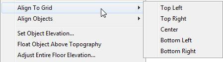
- On the Edit Toolbar, click the Selection Tool and then click to select the object or feature you want to align.
- Click Edit menu > Align to Grid, then click the area of the grid where you want your selection aligned.
To enable or disable Snap to Grid
When snap to grid is enabled, you can use the grid lines (and minor grid lines) as a reference to move selections based on those lines. Selections move based on the Snap Grid settings, which you can control by editing the grid settings
- Click 2D menu > Snap to Grid. The feature is enabled when a checkmark is visible and disabled when a checkmark is not visible.
(alternatively) Right-click the design window and click Snap to Grid on the context menu.
To configure grid settings
- Click 2D menu > Grid Properties. The Design Options dialog box opens to the Grid Settings. (alternatively) Right-click the design window and click Grid Properties on the context menu that is displayed (or press CTRL+G).
- Edit the grid settings and then click OK.
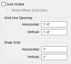
- Grid Visible checkbox controls whether the grid is visible (selected) or not (deselected). When the grid is visible, you can turn on or off the minor grid lines.
- Grid Style specifies the grid lines.
Note: Grid Lines can be set to as low as 1 inch (English), 0.02 m (Metric), and still be viewable. Grid Lines can be set as high as 500 inches (English), 12.70 m (Metric).
- Grid Lines Spacing defines the horizontal and vertical measurements for the grid. This is the distance between each grid line.
Note: Initially, the grid is set at 12 inches, making it easy to visualize each plan square as exactly one square foot, but can be customized to meet your particular design needs.
- Snap Grid defines the horizontal and vertical measurements for the minor grid lines. Items you draw or drag-and-drop into the design window snap to the measurements you’ve defined here.
Note: Snap settings can be set as low as 0.0625 (1/16 inch) English, 0.01 meter (1 cm) Metric, and still show visible movement along the grid. Snap settings can be set as high as 500 inches (English), 12.70 meter (Metric).
AutoSnap and Alignment Options
Snap points are automatically enabled as you design. Snap points are designated points or “hot spots” where your cursor can lock-in, for help with accurate placement. Laser alignment is also available for easily aligning segments as you draw. Laser alignment and auto snaps can be enabled or disabled on Properties tab while nothing is selected in your design. Even more snaps settings are available in the Preferences window.
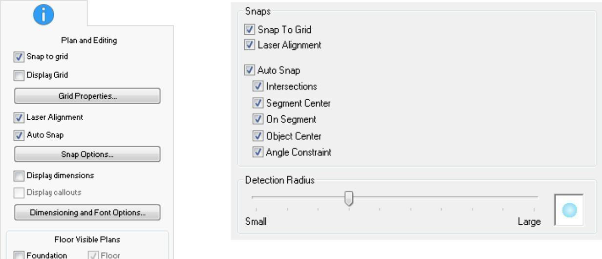
Auto Snaps
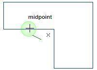
By default, when Auto Snaps are enabled the midpoint and end points are displayed when your cursor reaches these points. You can control these, and other “hot spots” or points, to which your cursor snaps on the Snap Options dialog box. Below, the midpoint snap point is displayed as the cursor is moved along a wall segment.

To control automatic snaps
- Click in the design window so nothing is selected and then, on the Properties tab, select the
Auto Snap checkbox to enable all snaps, or deselect to disabled all snaps.
To control individual snap points, click the Snap Options button and select the snap option(s) you want to enable, or deselect the snaps you want to disable and then click OK.
(alternatively) Click Edit menu > Preferences > Snap Settings.
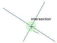
Intersections displays the intersection of two lines.
Segment Center displays the center point along a segment, as you drag.
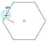
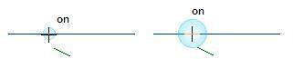
On segment displays when your cursor is actively on a segment, as you drag.
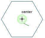
Object Center displays the center of an object as you drag to place within its bounds. A useful example would be centering a lamp on a table.
Angle Constraint locks a point to an adjacent segment’s angle. When selected, this also constrains a line angle to 1-degree increments as you draw.
Detection Radius Snap detection radius controls the size of the snap point detection area. To configure the detection radius, drag the slider to decrease or increase the detection radius.
Laser Alignment
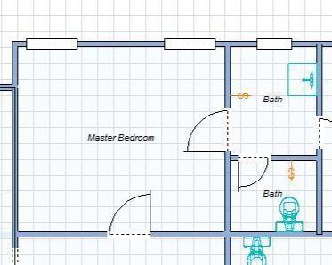
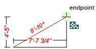
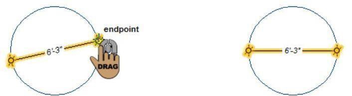
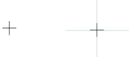
In addition to snap points, you can control the laser alignment, which is displayed when your cursor is in alignment with an existing point. In the example below, the cursor is positioned at the bottom of the drawing, where two end points align. When the cursor is positioned at one of the end points and laser alignment is enabled, the alignment is displayed.
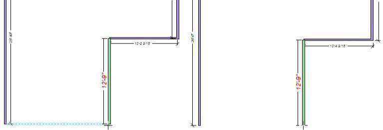
Laser alignment enabled Laser alignment disabled
To control laser alignment
- Click in the design window so nothing is selected and then, on the Properties tab, select the
Laser Alignment checkbox to enable alignment, or deselect to disable alignment. (alternatively) Click Edit menu > Preferences > Snap Settings.
3D and 2D Adjustments
If graphics are not properly displaying in 3D view window or you find 3D display issues (such as wrong textures resolution or placement), they can be overcome through changing the hardware acceleration.
- Click Edit menu > Preferences > System > 3D Graphics
Move the slider right to increase and left to decrease the hardware acceleration.
2D Anti-Aliasing will make 2D drawings smoother and clearer.
- To enable 2D Anti-aliasing, Click Edit menu > Preferences > System > 2D Graphics. Click the 2D Graphics check box.


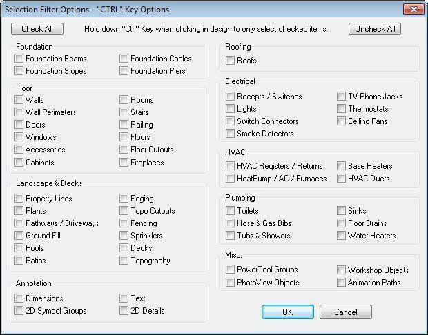
Selection Filter
There will be times when you will place items on top of each other. To make it easier to select each layer, use the Selection Filter. For example, to select a transom window, placed over a door, you can select “Windows” in the Selection Filter Options dialog box, and then when you hold down CTRL and click where the window and door are placed you will only select the window.
To filter selections
- Click 2D menu > Selection Filter Options (or press SHIFT+CTRL+S).
- Select the feature(s) you want to be able to select and then click OK to close the window. When you hold down CTRL, you will only be able to select those features.
Text Font
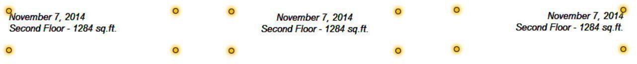
Use text to add information to your drawing. For example, you might add text to annotate rooms, specify a home address, the date the drawing was created, or a specific feature in your plan. This Software gives you the flexibility to place text anywhere in your plan drawing, using different formatting techniques for each text instance. Text you place in your drawing is displayed on all 2D printed output. The text tools are available on the Text & Dimension toolbar.
Rich Text Tool
Using the Rich Text Tool, you can add single or multi-line texts, rotated, as well as multiple fonts / sizes/ attributes in single text element. Also, the text color and transparency can be customized. You can assign drawing style to bounding box such as background fill and patterns to your design for annotations.When adding the text, you can edit the font properties by clicking the Font button or edit the font after text is placed.

To add Rich text
- On the Icon bar on the left of your project, click the Rich Text Tool and then click on the area of our project to define where your text will be displayed.
- Type the annotation in the text box. Press the ENTER key to move to the next line.
- Click OK to add the text to your design.
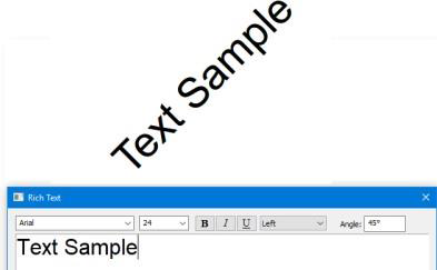
Rotated Text
Using the Rotated Text feature, you can add a single line of text at an angle for precise annotations.
To place text at an angle
- Choose the Text button from the Annotation Tools group and then click in the design window where you want to place text. A dialog appears.
- Enter the annotation in the field. Press the Return key to move to the next line.
- Enter the Rotation Angle you want.
- Click OK to place the text
Other Settings
Opening the Rich Tool screen, you can define the different fonts, sizes and styles by opening the drop-down menus
Edit Text and Text Properties
Once you’ve added text in your drawing you can edit the content, font properties, and alignment. When text is selected, the Text editing options are displayed on the Properties tab.
- The Edit button opens the Rich Text window, where you can edit the existing text as well as font properties, styles, fonts, etc.
- Click the Font button to edit the Font, Font Style, and Size.

- Align allows you to set the text justification for Left, Center, or Right (only available for Rich Text).
Align Left Align Center Align Right
Dimensioning

This Software automatically displays dimensions, as you draw, making it easy to precisely place walls, doors, and other items in your plan drawing. The powerful Dimension Wall Spacing Tool will be especially useful to add interactive dimensions between walls, where they are not automatically generated. Dimensions drawn with the Dimension Wall Spacing Tool are automatically updated when either wall is moved. You’ll find this tool extremely useful when measuring between the main house and the walls of other buildings, like a garden shed or playhouse. In some instances, you might want to print your plan drawing without dimension annotation. You have the option of turning off automatic dimensioning, if you don’t want it displayed on the drawing page or as you draw.
All Dimensioning tools can be found on the Text & Dimension toolbar on the left side of the application window. When the application window is resized to the point where all of the text and dimension tools cannot be displayed, the toolbar collapses. When collapsed, click the pop-up menu to see all of the tools.
To control automatic dimension display
- Click the design window so nothing is selected and then on the Properties tab, select the Display dimension checkbox to enable all dimensions, or deselect to disable all dimensions.
(alternatively) Click 2D menu > Automatic Dimensioning to enabled or disable dimensions.
When dimensions are enabled, you can select the Display callouts checkbox to enable window and door callouts or deselect to disable.
To control the display of room dimensions
- Click the center of the room you want to edit. The room is highlighted in yellow and the room properties are displayed on the Properties tab.
- Under Label, deselect the Dimensions checkbox to hide the room dimensions. To show the room dimensions, select the Dimensions checkbox.
To control the display of the room area
- Click the center of the room you want to edit. The room is highlighted in yellow and its properties are displayed on the Properties tab.
- Under Label, deselect the Area checkbox to hide the room area. To show the room area, select the Area checkbox.
To add a room name label
- Click the center of the room you want to edit. The room is highlighted in yellow and the room properties are displayed on the Properties tab.
- Under Label, select the Name checkbox and type to room name you want in the text box, then press ENTER. The name is added to the room label in the drawing.
- To hide the room name label, deselect the Name checkbox.
To control measurement unit indicators
- Click 2D menu > Dimensioning & Fonts. The Design Options open to the Dimensioning and Fonts settings.
- Click to select the Display measurement unit indicators checkbox to enable unit indicators in the design window or deselect to disable.
- Click OK.
Dimension Wall Spacing
This tool quickly places a dimension between two walls. The dimension must start along a wall but does not have to end at another wall. When you release, the dimension automatically extends to the nearest wall surface.
To place a wall spacing dimension
- On the Text & Dimension toolbar, click the Dimension Wall Spacing Tool.
- Use the Click-and-Drag drawing method to drag the dimension from one wall to another.
Zero-Offset Dimension
This creates dimensions from any point, surface, or object, even at angles.
To place a zero-offset dimension
- On the Text & Dimension toolbar, click the Zero-Offset Dimension Tool.
- Use the Click-and-Drag drawing method to drag from one object to another.
Offset Dimension
Offset dimensions are placed with the Offset Dimension Tool. This determines the horizontal or vertical distance between two points.
To place an offset dimension
- On the Text & Dimension toolbar, click the Offset Dimension Tool.
- Use the Click-and-Drag drawing method to drag the dimension from the start point of the measurement to the end point of the measurement. Release to set the dimension.
- Move the mouse in the direction you want the offset dimension to be placed and click to place the dimension.
Length Dimension
This allows you to measure the distance of a single segment by selecting the two end points, the dimension is positioned offset from the segment.

To place a length dimension
- On the Text & Dimension toolbar, click the Length Tool.
- Use the Click-and-Drag drawing method to drag the dimension from the start point of the measurement to the end point of the measurement. Release to set the dimension.
- Move the mouse in the direction you want the offset dimension to be placed and click to place the dimension.
Diameter Dimension
This allows you to measure the diameter of a circle by dragging along the circle’s perimeter, automatically detects the opposite edge and displays the dimension in the middle of the circle.
Note: This dimension applies to circles only; you cannot measure the diameter of an oval.
To place a diameter dimension 
- On the Text & Dimension toolbar, click the Diameter Dimension Tool.
- Use the Click-and-Drag drawing method to drag along the edge of the circle. The dimension automatically snaps to the opposite edge of the circle.
- Release to set the dimension.
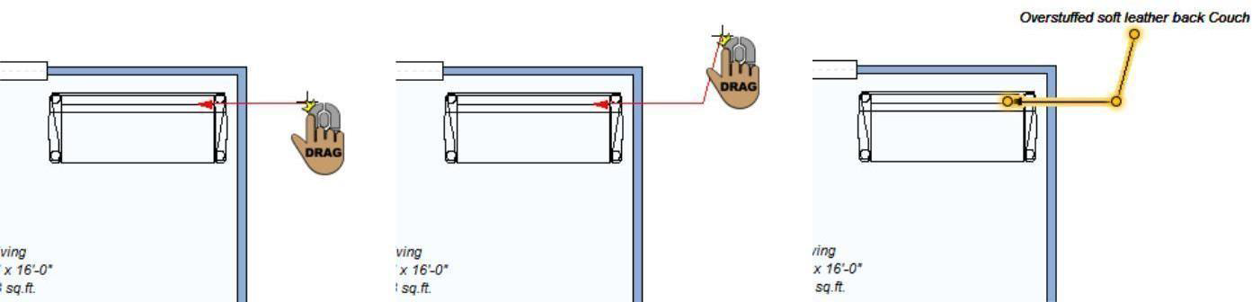
Leader Dimension
This allows you to annotate your workspace by positioning a single arrow and leader line between two objects, for example, when associating text with a 2D object. You can also automatically add a room’s area and name by pointing into an enclosed room. When you place a leader dimension on a component or object, the description is automatically detected for the annotation. You can edit this as needed.
Once placed, you can edit the label text, including font properties and alignment, as well as change the leader type and arrowhead style.
To place a leader dimension
- On the Text & Dimension toolbar, click the Leader Dimension Tool.
- Use the Click-and-Drag drawing method to set the position for the arrowhead and the first segment of the dimension.
- Release the mouse button and drag in the direction you want the second segment to be placed.
- Click to place the dimension. The Edit Text dialog box is displayed.
- Type the text you want to be displayed with the leader and then click OK. The text that is displayed is based on the leader type that is selected.
Leader Dimension Properties
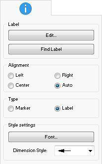
Leader dimensions can be customized by editing their text and alignment. You can also choose between a text label or a marker label and customize the arrowhead style. To edit leader dimension properties, use the Selection Tool to select the dimension in the design window. Its properties are displayed on the Properties tab.
- Edit button opens the Edit Text dialog box for the selected text where you can edit the text and font style. For more information, see “Edit Text and Text Properties”.
- Find Label button automatically detects the component description or object information for an item in your drawing and updates the leader label text to match. To accurately find the label, the leader dimension arrowhead must be position on the item in the design window.
For information on editing component descriptions.
- Alignment options allow you to set the text justification for Left, Center, Right, or Auto.
- Type specifies whether the leader dimension uses a marker or label.
- Marker displays an incremental number, with the leader text visible when you hover over it with your mouse. This saves space when there is a lot of text to be displayed.
- Label displays the leader text in the design window.
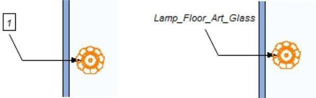
Marker Label
- Font button allows you to edit the Font, Font Style, and Size of the marker or leader text.
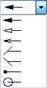
- Dimension Style drop-down menu allows you to choose the end point style for the leader dimension.

Dimension and Font Default Settings
There are a number of ways you can control and configure the dimensions and fonts that are displayed in your design.
The Dimensioning and Font properties are controlled in the Design Options dialog box. These are the default settings, so changes to the settings are applied to subsequent text or dimensions that are added to your design.
To access dimensioning and font properties
- Click an empty space in the design window so nothing is selected and then, on the Properties tab, click the Dimensioning and Font Options button.
(alternatively) Click 2D menu > Dimensioning & Fonts.
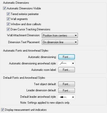
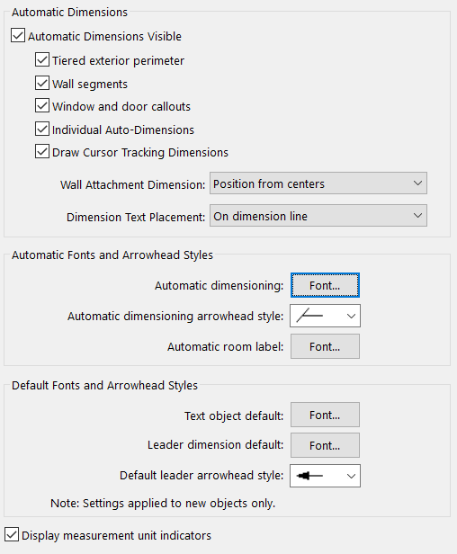
Automatic Dimensions
The Automatic Dimensions control the display of dimensions in your drawing. You can enable or disable different combinations of dimensions depending on your needs. You can also quickly enable or disable automatic dimensions from the Properties tab.
- Automatic Dimension Visible checkbox controls the display of the available dimensions. When selected, dimensions are visible and you can control the display of the available dimensions; when deselected all dimensions are disabled.
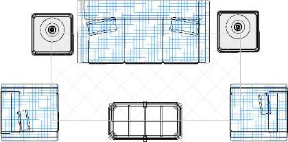
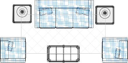
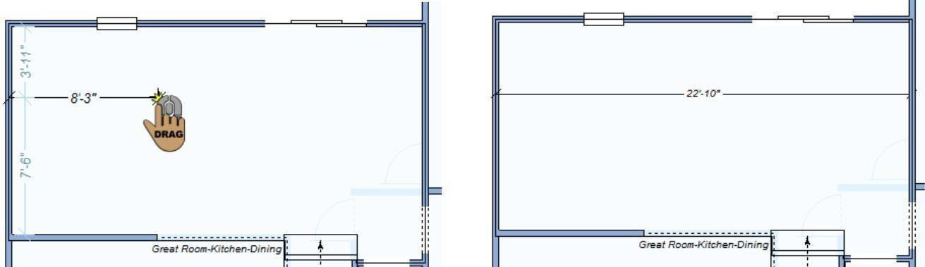
- Tiered exterior perimeter checkbox controls the display of wall dimensions that include more than one wall segment. When enabled, both the exterior wall segment dimensions and the total wall measurement are displayed.
When disabled, only the individual wall segment dimensions are displayed.
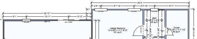
Tiered exterior perimeter disabled
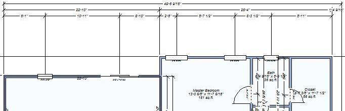
Tiered exterior perimeter enabled
- Wall segments controls the display of dimensions along wall segments. To control dimensions on individual walls, see “Wall Properties”.
- Window and door callouts controls the display of dimensions for windows and doors in the design. Select the checkbox to enable; deselect to disable.
(alternatively) You can also control callouts display by selecting or deselecting the Display callouts checkbox on the Properties tab while nothing is selected in the design window or click 2D Menu > Window and Door Callouts.
- Draw Cursor Tracking Dimensions controls the display of dimension lines from the cursor when a tool is selected. Select the checkbox to enable; deselect to disable.
Cursor Tracking Off Cursor Tracking On
Note: You can also control cursor dimensions display by right-click in the design window and choosing Cursor Dimensions or clicking 2D menu > Cursor Dimensions (dimensions are enabled when a checkmark is visible).
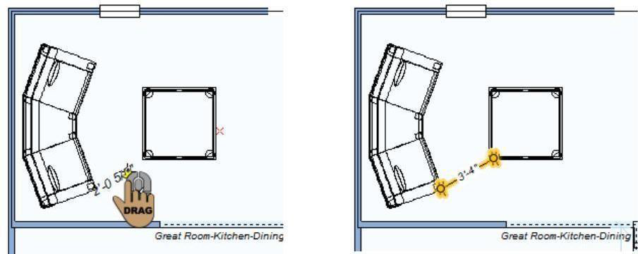
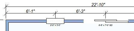
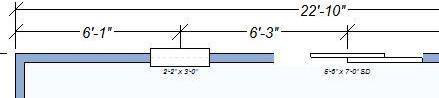
- Wall Attachment Dimension drop-down menu allows you to choose the position of wall attachment dimensions.
- Position from edges measures the distance between each edge of the attachment (its width) and the distance from each edge to the nearest wall.
- Position from centers measures the distance from the center of the attachment to the nearest wall on either side.
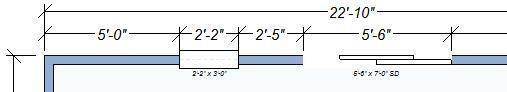
Position from edges
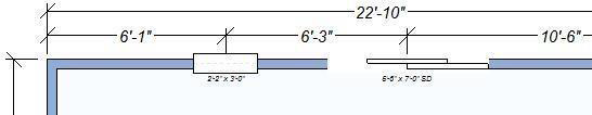
Position from centers
- Dimension Text Placement drop-down menu specifies how you want dimension text positioned.
- Above dimension line positions dimension text above the dimension line.
- On dimension line positions dimensions text along the dimension line.
Above dimension line
On dimension line
Automatic Fonts and Arrowhead Styles
The Automatic Fonts and Arrowhead Styles settings control the look and feel of the automatic dimensions in your drawing. When automatic dimensions are enabled, these settings are applied.
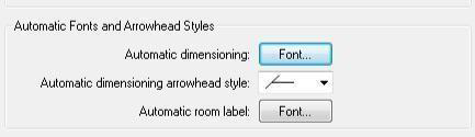
- Automatic dimensioning Font button opens the Font dialog box. These settings control the font used for automatic dimensions. For more details on font settings, see “Edit Text and Text Properties”.
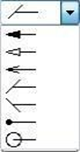
- Automatic dimensioning arrowhead style drop-down menu provides access to the available end point styles.
- Automatic room label Font button opens the Font dialog box. These settings control the font used for room labels when the Label Name is enabled. For more details on font settings, see “Edit Text and Text Properties”.
Default Fonts and Arrowhead Styles
The Default Fonts and Arrowhead Styles settings control the look and feel of the dimensions and text you add in your drawing using the text and dimensioning tools.
- Text object default Font button opens the Font dialog box. These settings control the font used for text added using the text tools.
- Leader dimension default Font button opens the Font dialog box. These settings control the font used for text associated with leader dimensions.
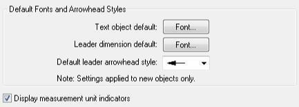
- Default leader arrowhead style drop-down menu provides access to the available end point styles for leader dimensions. The default is applied to all leader dimensions.
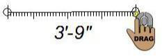
The Virtual Ruler
The Virtual Ruler works like a real-world tape measure and is a handy feature for measuring items in your home plan that are not automatically dimensioned.
When active, it is displayed in the middle of the window, where you can move it into any position necessary to make a needed measurement. To move the Virtual Ruler, click and drag from the center. To resize, click and drag on one of the ends. You are not constrained to vertical or horizontal; the Virtual Ruler can be stretched in any direction necessary.
To measure using the Virtual Ruler
- Click 2D menu > Show Virtual Ruler. The Virtual Ruler is displayed on the design window. (alternatively) Right-click the design window and choose Center Virtual Ruler.
- Click-and-drag an end in the direction you want to measure. The measurement is displayed in the center of the Virtual Ruler.
(optional) Click-and-drag the Virtual Ruler from its center to move it to a new location on the design window.
Tip: Zoom in on the area you are measuring so you have a close-up view of the ruler.
To hide the Virtual Ruler
- Click 2D menu > Show Virtual Ruler to uncheck the option.
(alternatively) Right-click the Virtual Ruler and click Hide Virtual Ruler on the context menu.
Screen Colors
You can assign custom colors to areas of your design, such as plans, inactive floors, grid line colors, and the color of your crosshair. These color settings and more, can be customized by accessing the 2D menu.
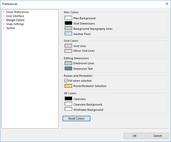
To change a design color
- Click 2D menu > Screen Colors. The Preferences dialog box is opened to the Design Colors settings.
- Click the thumbnail of the color you want to change. The Color dialog box is displayed.
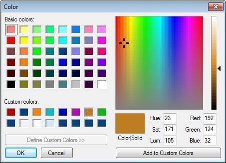
- Click a color from the Basic colors, Custom colors, or the color matrix.
Note: The Color Solid preview box displays the chosen color.
(optional) On the right side of the dialog box, move the arrow next to the color bar to define the luminosity or type values in the Hue, Saturation, and Luminosity variables text boxes or RGB text boxes.
- Click OK and then click OK in the Preferences window.
To reset all colors
- Click 2D menu > Screen Colors and click the Reset Colors button. All colors will be reset to the default values. Click OK to close the window.
Draw Style Tab
The Draw Styles tab contains different formatting tools for lines, shapes and texts, allowing the change of thickness, addition of patterns and colors as well as the adjustment of the transparency.
The Draw Style Profiles allow for customization of the drawing style defaults for each type of object / component. If a draw style profile does not exist for a certain object type, the Draw style for the Plan will be used.
Line weight
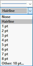
You can choose a predefined line weight from the Weight button drop-down menu or specify a value up to 20pt. To edit the line weight, you must select the element first.
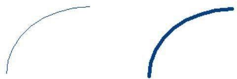
Line Weight 1pt Line Weight 6pt
To change/specify the line weight
- Click the “Select / Move Objects Tool” and then click to select the element you want to edit.
- On the Draw Style Tab, click the Weight drop down menu and choose one of the available sizes.
- You can also choose Other from the drop-down menu and type a value in the Points text box or click the arrows to edit incrementally and then click OK.
Line Style
You can choose a predefined line style from the Line Style button drop-down menu. To edit the line style, you must select the element first.

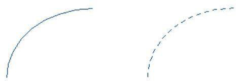
Solid Style Dotted Style
To change the line style
- Click the “Select/ Move Objects Tool” and then click to select the element you want to edit.
- On the Draw Style Tab, click on the Line Style drop down menu and choose one of the available sizes.
Line text styles


Add labels to line styles. Allow for labeling systems such as HVAC, electrical, plumbing runs. Additional text styles available through downloadable content or create your own.
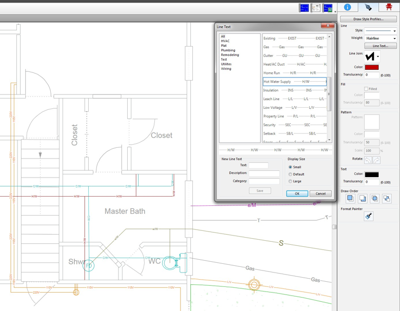
To change the line text
- Click the “Select/ Move Objects Tool” and then click to select the element you want to edit.
- On the Draw Style Tab, click on the Line text button and choose one of the line text style.
3. You can change text size by switching radio button in Display Size.
4. You can add Custom text by filling Text, Description and Category in New Text Line section.
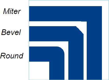
Line join
You can choose a predefined line cap styles (miter, bevel, rounded) from the Line Join drop-down menu. To edit the line cap style, you must select the element first.

To change the line cap style
- Click the “Select/ Move Objects Tool” and then click to select the element you want to edit.
- On the Draw Style Tab, click on the Line Join drop down menu and choose one of the available styles.
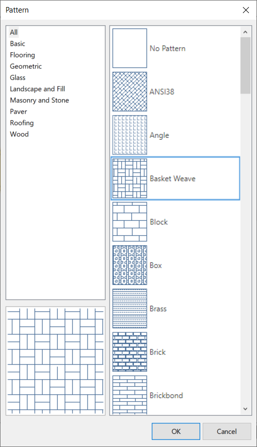
Fill pattern
You can change a shape’s fill pattern to be transparent, a solid color, or a patterned fill. You can rotate pattern as well. Fill patterns added along with support for expandable fill pattern library through downloadable content
The fills, from left to right, include:
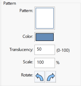
- Transparent
- Filled
- Solid Filled
- Patterns
To change the shape fill
- Click the “Select/ Move Objects Tools” and then click to select the element you want to edit.
- On the Draw Style Tab, click on the Pattern drop down menu and choose the available options.
- Patterns can be rotated by clicking arrow buttons.
- Color and Transaprency can be changed by using Color and Translucency scale respectively.
Controlling Drawing Order
You can control the position of an item by moving it to the front or back of another element

To control shape order
- Click the "Select / Move Objects Tool" and then click to select the element you want to edit.
- On the Draw Style Tab, click on one of above draw orders to change the position of the selected object.
Format Painter
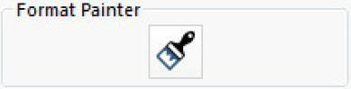
Use the Format Painter to quickly apply the settings defined on the Draw Style Tab.
To Apply Format Painter
- Select the text or graphic that has the formatting that you want to copy then click on the Format Painter tool > the pointer will change to a paintbrush icon.
- Click on the desired texts or graphics > the tool will apply the original formatting to selected elements.
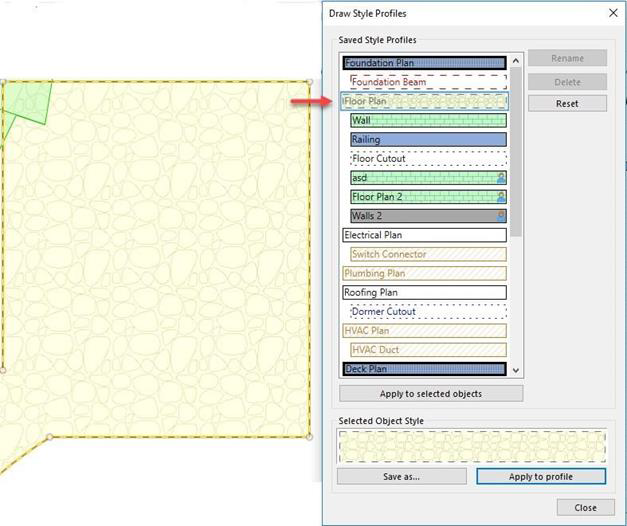
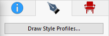
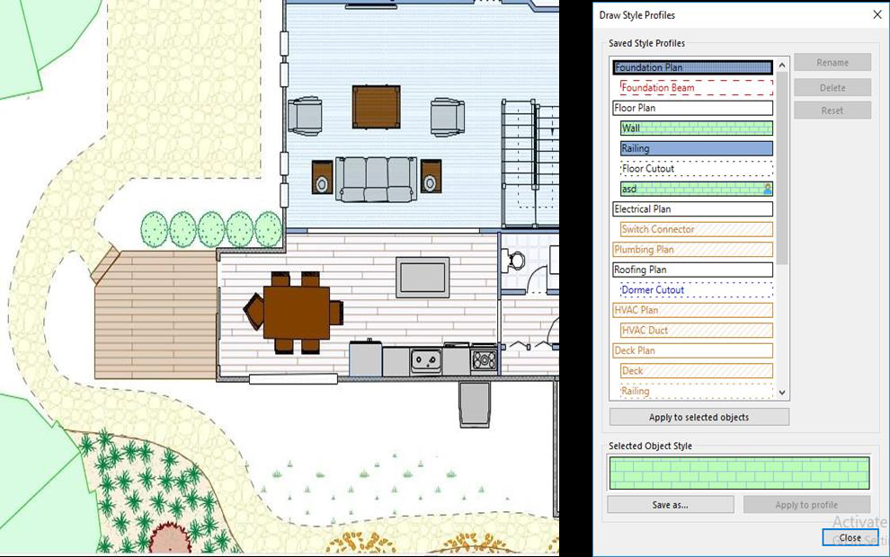
Draw Style Profile
Draw Style Profiles allow for customization of the drawing style defaults for each type of element or component. If a draw style profile does not exist for an element type, the draw style for the Plan will be used. You can choose a predefined draw style profile by clicking on the Draw Style Profiles Button.
To Apply the Draw Style Profile
- Click the "Select / Move Objects Tool" and then click to select the element you want to apply the style.
- On the Draw Style Tab, click the Draw Style profile button and choose one of the styles from the dialog and double click on it to apply.
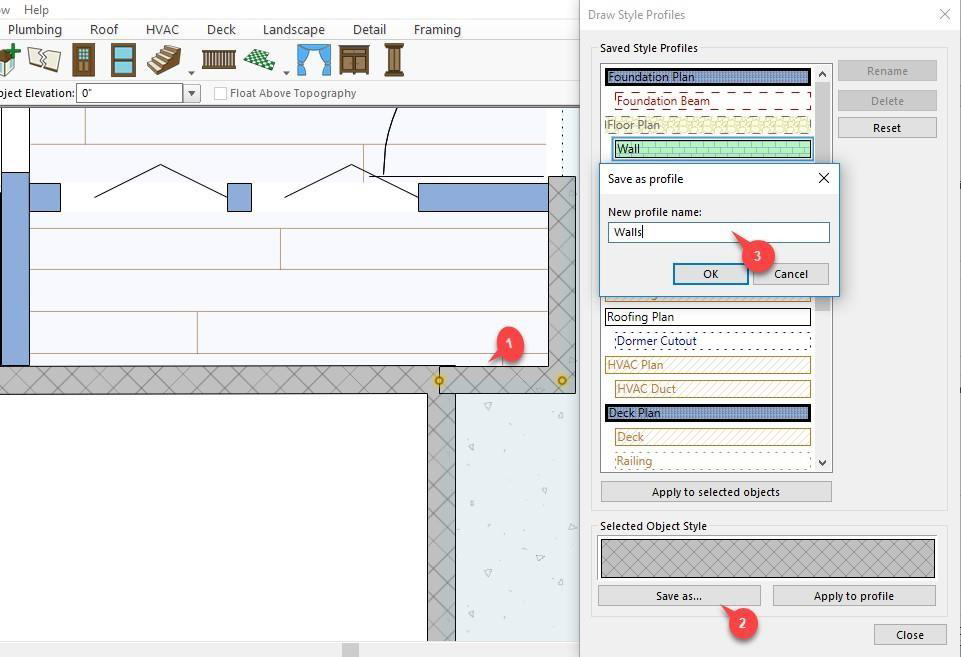
To save a new profile
To save a new profile select the object in 2D that contains the draw style you would like to save and open the Draw Style Profile dialog. Choose Save as and name your new profile. The draw style you saved will now be used as the default for new objects of the selected type on that plan. For example, if the selected object is a wall that is assigned to the Floor Plan then all new walls added to the Floor Plan will use the saved profile.
To update an existing profile
To edit a saved Draw Style Profile > select an object with the desired draw style settings you would like to use >open the Draw Style Profile dialog. Select the saved profile you wish to update and choose Apply to profile.