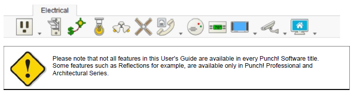
Electrical Plan Tab
Adding electrical components to your home design is a simple matter of selecting the component you want to place and clicking on your drawing plan. You can even turn the lights on and off!
Punch! Home & Landscape Design Software provides handy placement features, such as associative dimensioning and wall tracking. Using associative dimensioning, you can place components a specific distance from a neighboring wall or other electrical component. Automatic wall tracking makes sure you place components, such as outlets and switches, without error.
Placing Receptacles
Punch! Home & Landscape Design Software makes it simple to add electrical components to your home plan.
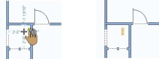
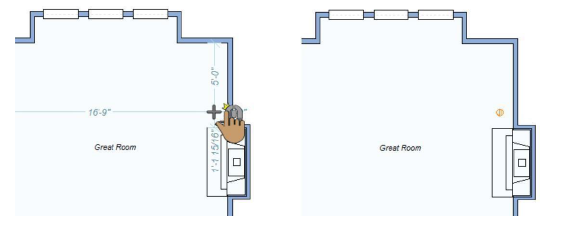
Using the convenient tabbed utility tools, simply select the components you want to place and click. Dimension lines automatically appear, making it easy to place components a specific distance from a neighboring electrical component or wall segment.
You’ll notice that when placing certain outlets and switches, the component is automatically “tracked” to the wall segment, making accurate placement simple. Floor and ceiling outlets are not tracked to walls.
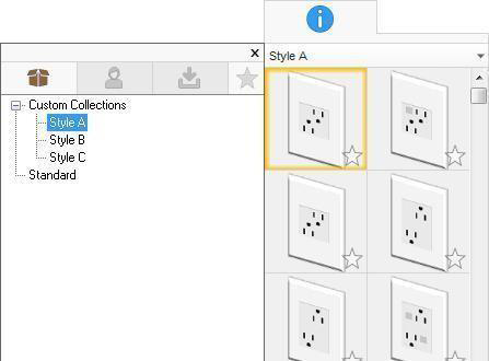
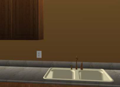
While a receptacle tool is active, or a receptacle is selected in your drawing, you can choose a receptacle style on the Properties tab. From the drop-down menu, choose a Custom or Standard library and then select the style you want on the
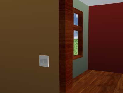
Preview Bar. The receptacle in your drawing is updated, and you can see the style in the 3D view. The Wall Receptacle library is shown here, however the Floor Receptacle and Ceiling Receptacle libraries are organized similarly.
Note: As you hover over each preview, its description is displayed.
You can further customize receptacles and switches using the following editing methods:
- 2D Editing Methods
- Elevating Objects
- Component Description
- Applying Paint and Color
- Working with 3D Views
Wall Receptacle
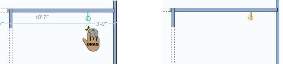
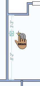
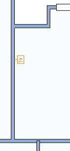
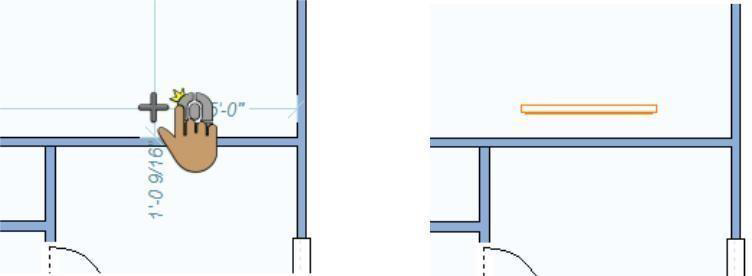
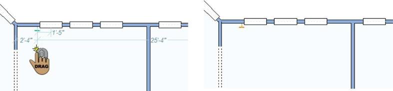
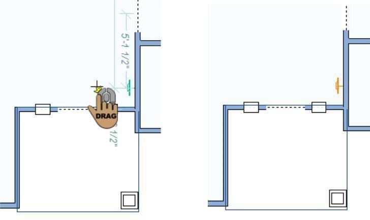
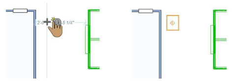
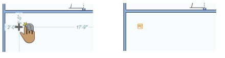
Wall receptacles are tracked along walls. Dimensions are displayed as you drag the receptacle along the wall, indicating the distance from the center of the receptacle to the nearest wall or other electrical component.
You can choose the style you want on the Properties tab when the Receptacle tool is active or a receptacle is selected in your drawing.
To place a wall receptacle 
- On the Electrical plan toolbar, click the Wall Receptacle Tool from the Receptacle toolset.
- Use the Drag Along Wall drawing method to position the receptacle on the side of a wall where you want it and release to place.
Floor Receptacle
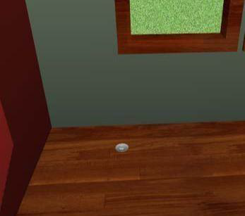
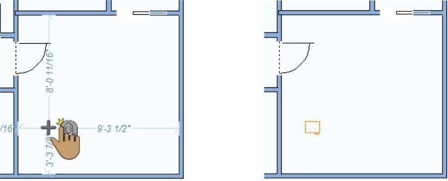
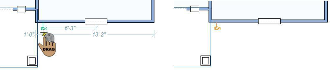
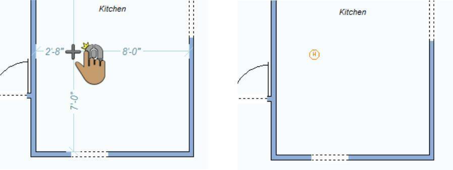
Floor receptacles are placed on the floor surface. Dimensions are displayed as you move the cursor around the design window, indicating the distance from the center of the receptacle to the nearest wall or other electrical component.
If an auto-floor is detected, the receptacle is placed at an elevation that considers the auto-floor depth. If changes are made to the auto-floor depth after a floor receptacle is placed, the receptacle’s elevation also needs to be adjusted.
You can choose the style you want on the Properties tab when the Receptacle tool is active or a receptacle is selected in your drawing.
To place a floor receptacle 
- On the Electrical plan toolbar, click the Floor Receptacle Tool from the Receptacle toolset.
- Use the Click Once to Place drawing method to place the receptacle in your design.
Ceiling Receptacle
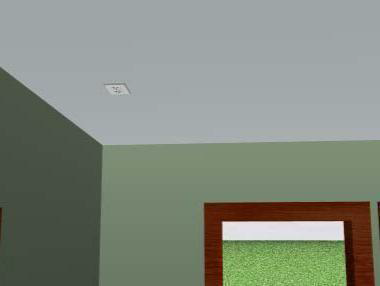
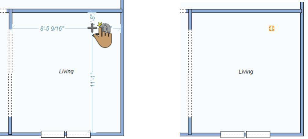
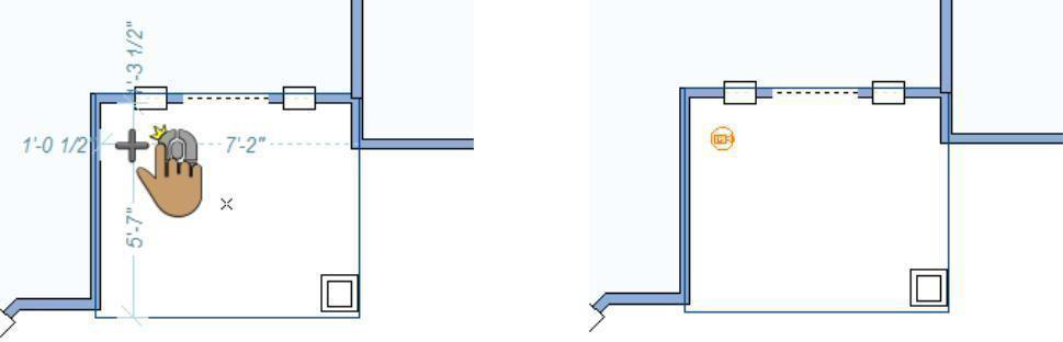
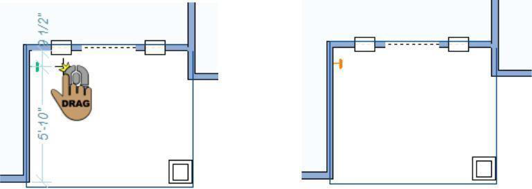
Ceiling receptacles are placed on the ceiling surface. Dimensions are displayed as you move the cursor around the design window, indicating the distance from the center of the receptacle to the nearest wall or other electrical component.
Ceiling receptacles are placed at the auto-ceiling elevation. If the ceiling for a room is disabled, it is placed at 0 by default. You can then adjust the receptacle elevation as needed.
You can choose the style you want on the Properties tab when the Receptacle tool is active or a receptacle is selected in your drawing.
To place a ceiling receptacle
1- On the Electrical plan toolbar, click the Ceiling Receptacle Tool fromthe Receptacle toolset.
2- Use the Click Once to Place Drawing method to place the receptacle in your design.
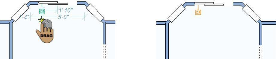
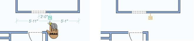
Wall Switch
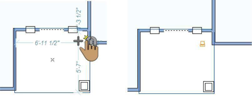
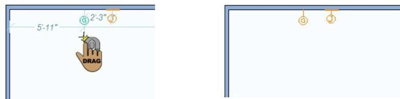
Switches are tracked along walls. Dimensions are displayed as you drag the switch along the wall, indicating the distance from the center of the receptacle to the nearest wall or other electrical component.
You can choose the style you want on the Properties tab when the Switch Tool is active or a switch is selected in your drawing
To place a switch 
-
On the Electrical plan toolbar, click the Switch Tool.
-
Use the Drag Along Wall drawing method to position the switch on the side of a wall where you want it and release to place.
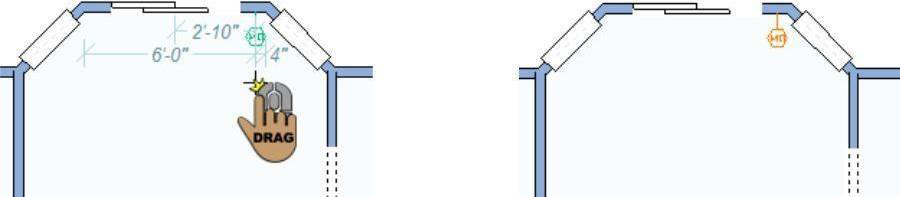
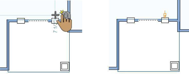
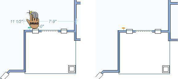
Switch Connector Tool
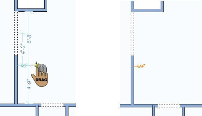
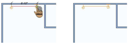
It’s easy to add switch connectors to your home design. Using the Switch Connector Tool, just click and drag to define the connection. Once placed you can move a switch connector by dragging the entire segment or one of the end points. Connectors are only visible in the 2D view.
To place a switch connector 
-
On the Electrical plan toolbar, click the Switch Tool.
-
Use the Click-and-Drag drawing method to draw from a switch or electrical component to another electrical component and release to place the connector.
Note: Hold down the SHIFT key while drawing to constrain to a perfect arc.
Adding Lighting
You can add interior and exterior lighting to your design with just a couple of mouse clicks. Each light has its own properties so you can control settings individually. The following lighting options are available:
- Fixture Lights
- Flood Lights
Below are some references that may be helpful as you design:
- Light Properties
- 2D Editing Methods
- Elevating Objects
- Adding Lighting and Shadows
- Working with 3D Views
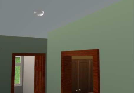
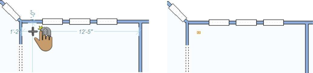
Fixture Lights
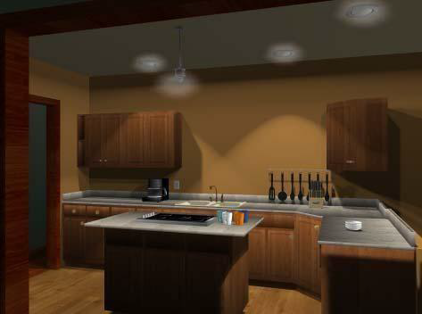
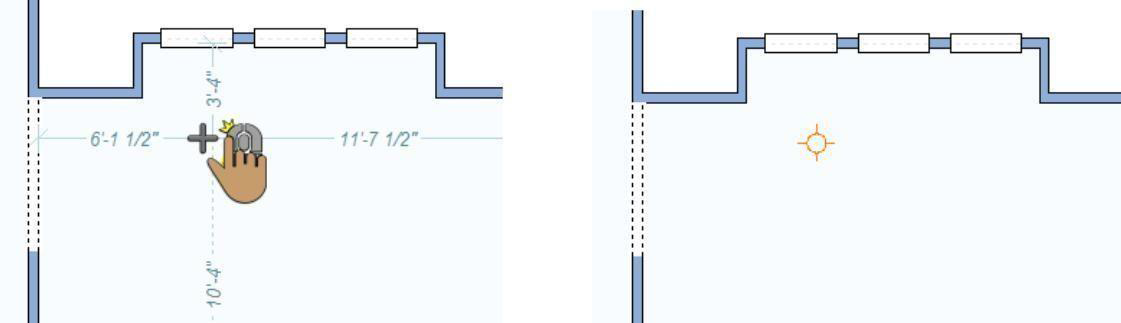
Adding fixture lighting to your design is very similar to adding other electrical components; however, they do not track directly to walls or automatically display dimensioning.
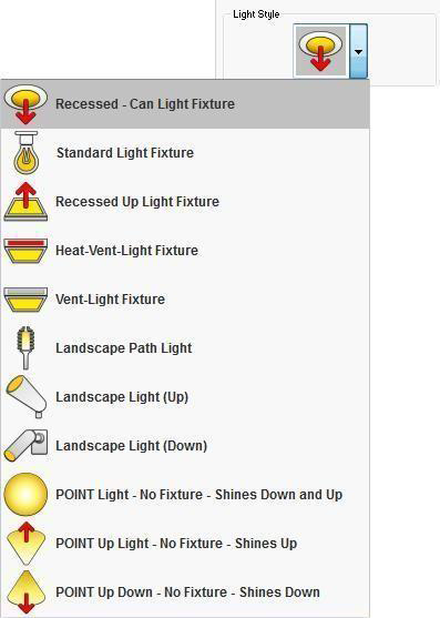
Punch! Home & Landscape Design Software provides many light styles to choose from, including recessed canned lights, heat/ vent lights, directional lights, even landscape lights. In addition, you can control the type and intensity of illumination that each fixture generates.
Before placing a light fixture in your drawing, choose a Light Style on the Properties tab. Once the light is place, its style cannot be changed.
To add a fixture lighting 
- On the Electrical plan toolbar, click the Fixture Light Tool.
- Choose the light style on the Properties tab.
- Use the Click Once to Place drawing method to place the light in your design.
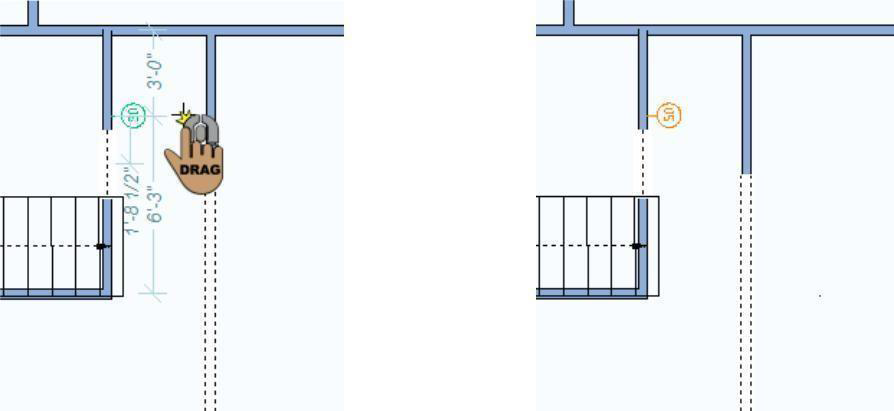
Flood Lights
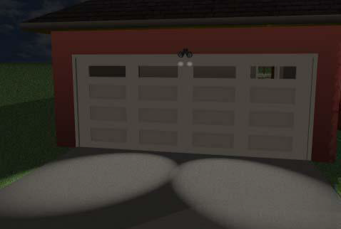
Flood lights are added just like outlets and switches; they attach to and track along walls and their lighting, which can be turned off and on, is displayed in 3D View. You can change the flood light’s elevation or position after it has been placed.
To add a flood light 
-
On the Electrical plan toolbar, click the Flood Light Tool.
-
Use the Drag Along Wall drawing method to position the light on the side of a wall where you want it and release to place.
Light Properties
Lights are defined by their beam and glow. You can edit the properties before you draw or after the component has been added to your design by selecting it and clicking the Properties tab. Changes to light settings are visible in the 3D view.
Note: When editing settings, always click the Apply button to accept changes.
- Beam checkbox controls the visibility of the beam dispensed by the light fixture. When selected, the beam displayed in the 3D view; when deselected the beam is not visible.
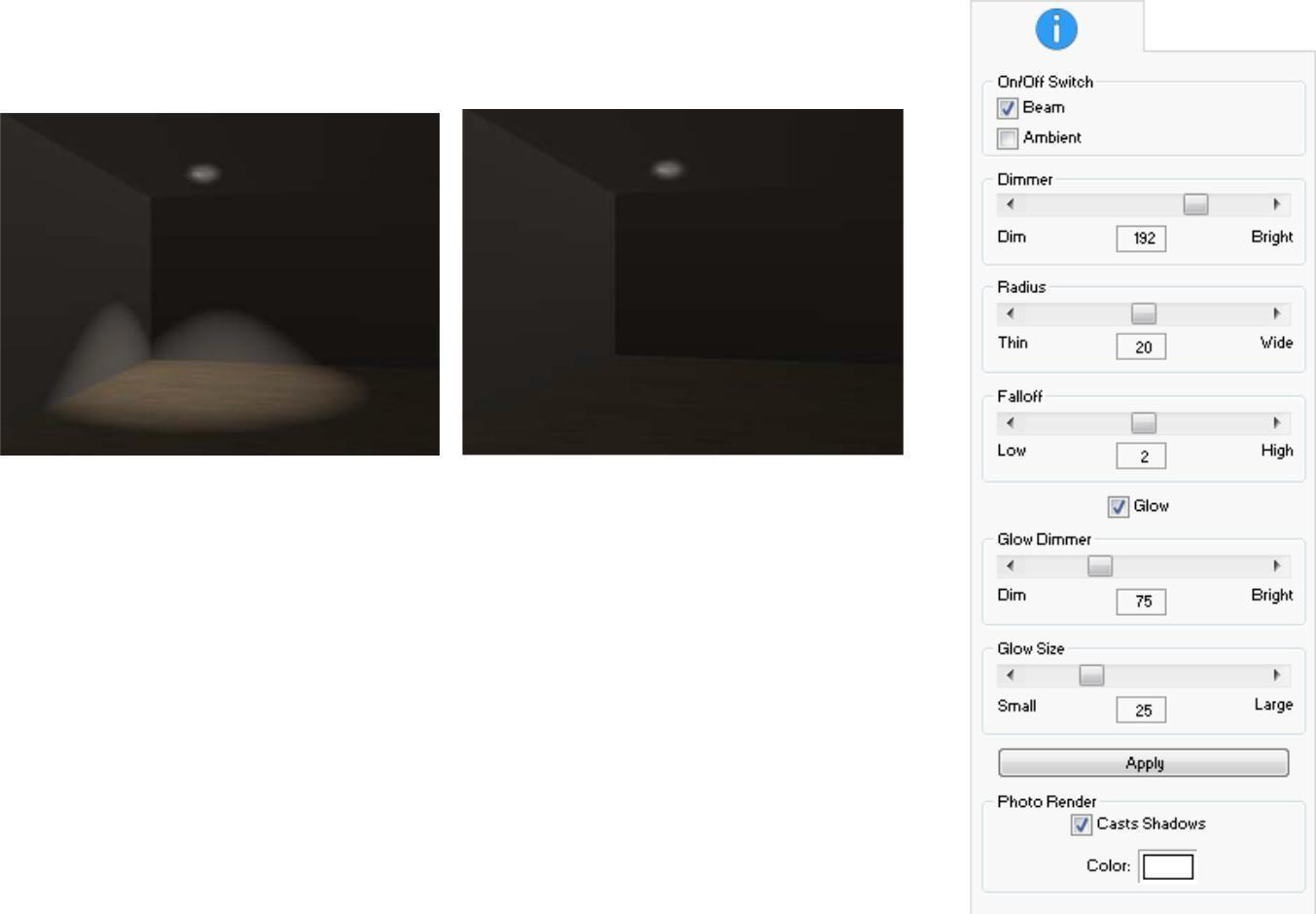
- Ambient checkbox controls the visibility of ambient light in the room. When selected, ambient light is displayed in the 3D view; when deselcted ambient light is not visible.
Ambient On Ambient Off
- Dimmer slider controls the brightness of the beam. Drag the slider or click the left and right arrows to decrease or increase the brightness.
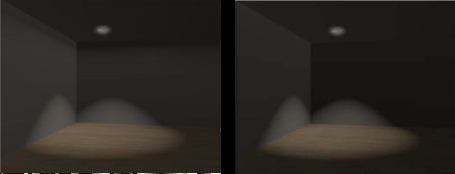
- Radius slider controls the size of the beam. Drag the slider or click the left and right arrows to decrease or increase the radius size.
Radius 5 Radius 30
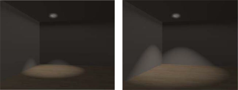
- Falloff slider controls the how diffused the edges of the beam are displayed. Drag the slider or click the left and right arrows to decrease or increase the amount of diffusion. The lower the falloff the sharper the edges; the higher the falloff the more diffused the edges.
Falloff 0 Falloff 4
- Glow checkbox controls the glow at the light source. When selected, the glow is visible at the light source; when deselected the glow is not visible. When the glow is enabled, you can edit the following settings:
- Glow Dimmer slider controls the brightness of the glow. Drag the slider or click the left and right arrows to decrease or increase the brightness.
- Glow Size slider controls the size of the glow. Drag the slider or click the left and right arrows to decrease or increase the glow size.
- PhotoRender settings are applied when rendering your 3D view using Photo Realistic Rendering mode. To see the Photo Render settings, you must render the view.
- Casts Shadows checkbox controls whether shadows are rendered. When selected, objects cast shadows; when deselected shadows are excluded.
- Color preview controls the color of the light that is generated. Click the preview to open to Color window, where you can choose the color you want.
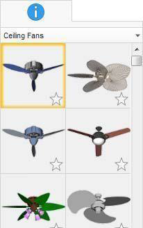
Adding a Ceiling Fan
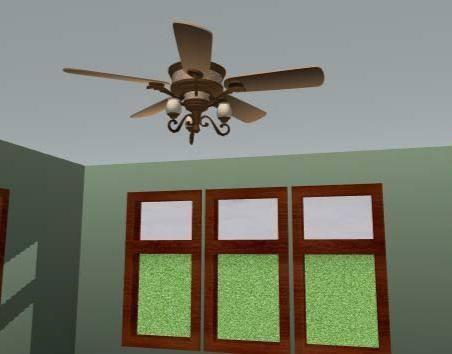
Placing ceiling fans is as simple as one mouse click. Once you place a ceiling fan, you can move it by dragging or by specifying exact coordinates.
The available ceiling fan styles are displayed on the Properties Bar when the Ceiling Fan Tool is active or when a ceiling fan is selected in your drawing. You can change the ceiling fan style by selecting the style you want in the Preview Bar.
Below are some references that may be helpful as you design:
■ AutoSnap and Alignment Options
■ Elevating Objects
■ Component Description
■ Applying Paint and Color
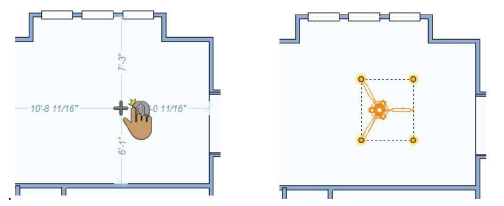
To add a ceiling fan 
1- On the Electrical plan toolbar, click the Ceiling Fan Tool
2- Use the Click Once to place drawing method to place the ceiling fan in your design
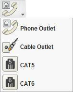
Placing Phone and Cable Outlets
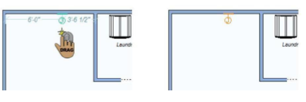
Placing phone and cable jacks is exactly like placing wall outlets and switches. You’ll notice that when placing jacks, the component is automatically “tracked” to the wall segment, making accurate placement simple. The phone or cable jack is displayed with dimensions as you drag to position it along the wall, which indicate the distance from the center of the jack to the nearest wall or other electrical component.
The following jacks are available in the Outlet toolset.
Below are some references that may be helpful as you design:
- 2D Editing Methods
- Elevating Objects
- Applying Paint and Color
To place a phone or cable outlet
-
On the Electrical plan toolbar, click the jack you want from the Outlet toolset.
-
Use the Drag Along Wall drawing method to position the jack on the side of a wall where you want it and release to place.
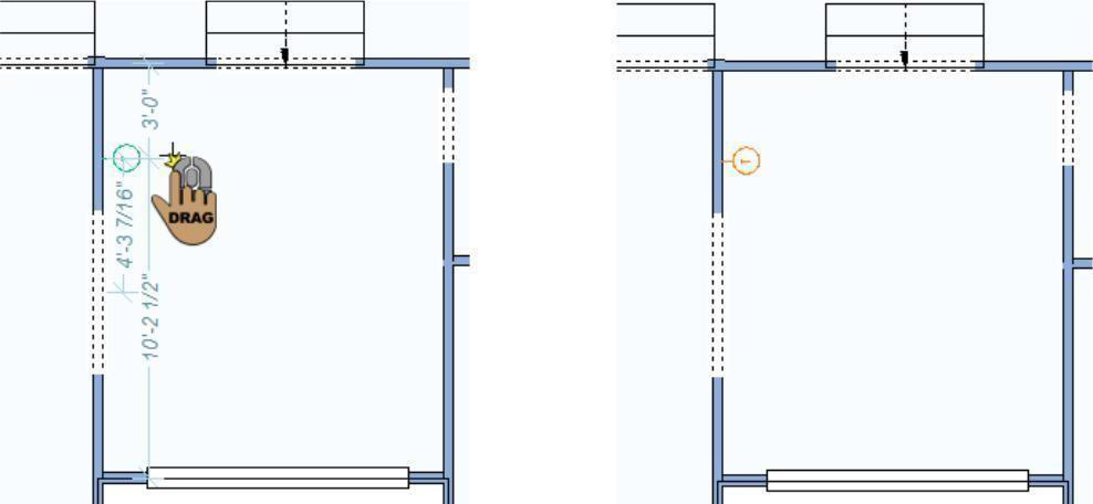
Adding Smoke Detectors
Smoke detectors can be placed either along a wall or on a ceiling.
The smoke detector is displayed with dimensions, as you drag along a wall or move the cursor around the design window, which indicate the distance from the center of the component to the nearest wall or other electrical component.
Below are some references that may be helpful as you design:
- 2D Editing Methods
- Elevating Objects
- Applying Paint and Color
To place a smoke detector on a wall 
- On the Electrical plan toolbar, click the Smoke Detector Tool.
- Use the Drag Along Wall drawing method to position the smoke detector on the side of a wall where you want it and release to place.
To place a smoke detector on a ceiling 
-
On the Electrical plan toolbar, click the Smoke Detector Tool.
-
Use the Click Once to Place drawing method to place the smoke detector in your design.
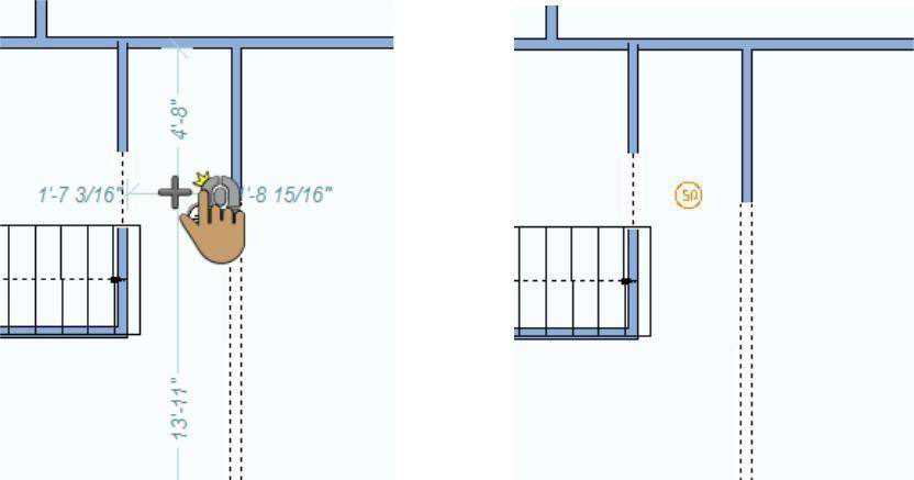
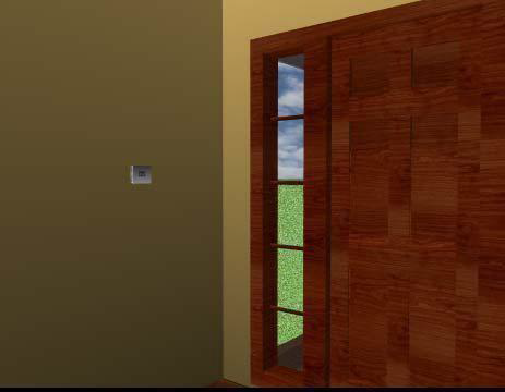
Adding Thermostats
Placing thermostats is exactly like placing wall outlets and switches. You’ll notice that, when placing, the component is automatically “tracked” to the wall segment, making accurate placement simple.
Below are some references that may be helpful as you design:
- 2D Editing Methods
- Elevating Objects
- Applying Paint and Color
To place a thermostat 
- On the Electrical plan toolbar, click the Thermostat Tool.
- Use the Drag Along Wall drawing method to position the thermostat on the side of a wall where you want it and release to place.
Adding Home Theater Components
Creating and customizing your home theater couldn’t be easier. There is an entire set of tools available to add audio and video components to your design, with just a couple of mouse clicks. These components have default elevations and orientations. For example, the Video Projector Tool attaches the video projector to the ceiling. You can reposition any of the home theater components using basic editing techniques.
The home theater components are displayed with dimensions, as you drag along a wall or move the cursor around the design window, which indicate the distance from the center of the component to the nearest wall or other components in the design.
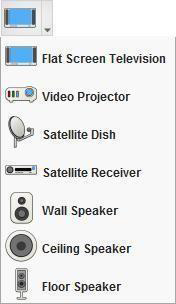
The toolset shown to the right displays the available components in the Home Theater toolset.
Below are some references that may be helpful as you design:
- Rotating a Selection
- Elevating Objects
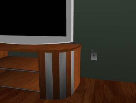
To add a flat screen television 
- On the Electrical plan toolbar, click the Flat Screen Television Tool from the Home Theater toolset.
- Use the Click Once to Place drawing method to place the component in your design. By default, the television is placed on the floor.
To add a video projector 
- On the Electrical plan toolbar, click the Video Projector Tool from the Home Theater toolset.
- Use the Click Once to Place drawing method to place the component in your design. By default, the television is placed on the floor. By default, the video projector is attached to the ceiling, based on the default ceiling height.
To add a satellite dish 
- On the Electrical plan toolbar, click the Satellite Dish Tool from the Home Theater toolset.
- Use the Click Once to Place drawing method to place the component in your design. By default, the satellite dish is placed at ground level.
To add a satellite receiver 
- On the Electrical plan toolbar, click the Satellite Receiver Tool from the Home Theater toolset.
- Use the Click Once to Place drawing method to place the component in your design. By default, the receiver is placed on the floor.
To add wall speakers 
-
On the Electrical plan toolbar, click the Wall Speaker Tool from the Home Theater toolset.
-
Use the Drag Along Wall drawing method to position the wall speaker on the side of a wall where you want it and release to place.
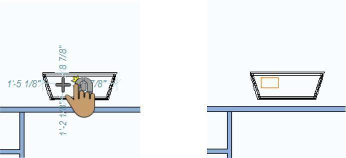
To add ceiling speakers 
-
On the Electrical plan toolbar, click the Ceiling Speaker Tool from the Home Theater toolset.
-
Use the Click Once to Place drawing method to place the component in your design. The ceiling speaker is placed based on the auto ceiling elevation.
To add floor speakers 
- On the Electrical plan toolbar, click the Floor Speaker Tool from the Home Theater toolset.
- Use the Click Once to Place drawing method to place the component in your design.
Adding Home Security Components
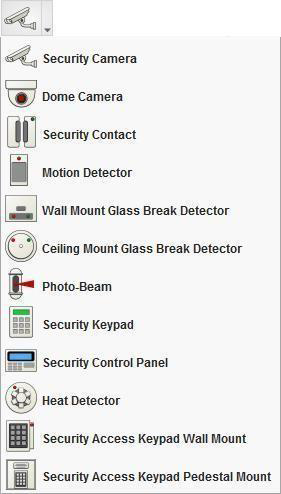
Home security components are available to suit all levels of security, from light and heat detection to cameras and control panels. These components have default elevations and orientations. For example, the Dome Camera Tool attaches a camera to the ceiling. You can reposition any of the home security components using basic editing techniques.
The home security components are displayed with dimensions, as you drag along a wall or move the cursor around the design window, which indicate the distance from the center of the component to the nearest wall or other components in the design.
The toolset shown to the right displays the available components in the Home Security toolset.
Below are some references that may be helpful as you design:
- Rotating a Selection
- Elevating Objects
To add a security camera to a wall 
-
On the Electrical plan toolbar, click the Security Camera Tool from the Home Security toolset.
-
Use the Drag Along Wall drawing method to position the component on the side of a wall where you want it and release to place.
To add a dome camera to a ceiling 
- On the Electrical plan toolbar, click the Dome Camera Tool from the Home Security toolset.
- Use the Click Once to Place drawing method to place the component in your design. By default, the dome camera is attached to the ceiling, based on the auto ceiling elevation.
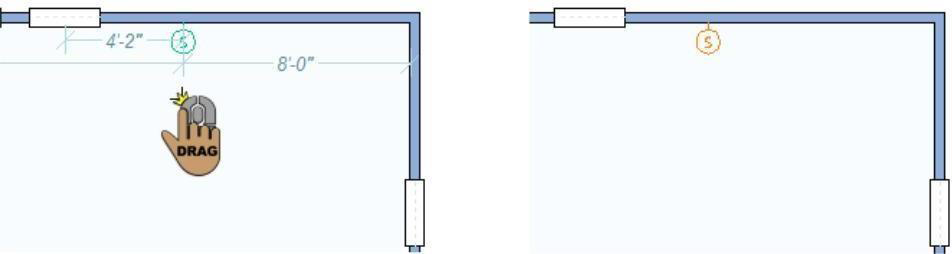
To add a security contact 
-
On the Electrical plan toolbar, click the Security Contact Tool from the Home Security toolset.
-
Use the Drag Along Wall drawing method to position the component on the side of a wall where you want it and release to place.
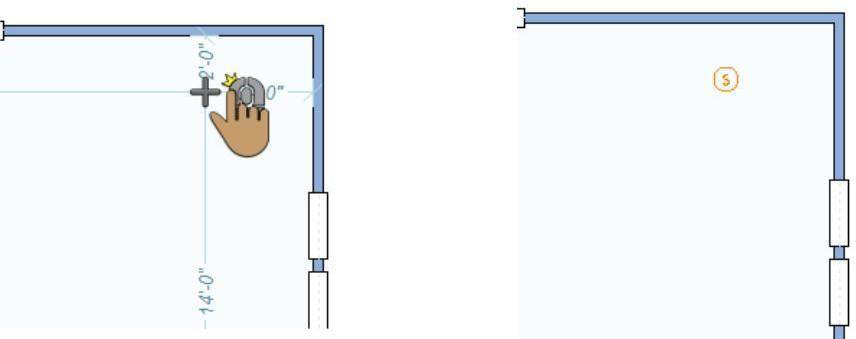
To add a motion detector 
- On the Electrical plan toolbar, click the Motion Detector Tool from the Home Security toolset.
- Use the Drag Along Wall drawing method to position the component on the side of a wall where you want it and release to place. The motion detector is placed at a default elevation near the ceiling.
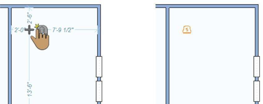
To add a wall-mounted glass break detector 
- On the Electrical plan toolbar, click the Wall Mount Glass Break Detector Tool from the Home Security toolset.
- Use the Drag Along Wall drawing method to position the component on the side of a wall where you want it and release to place. The glass break detector is placed at a default elevation on the wall.
To add a ceiling-mounted glass break detector 
- On the Electrical plan toolbar, click the Ceiling Mount Glass Break Detector Tool from the Home Security toolset.
- Use the Click Once to Place drawing method to place the component in your design.
By default, the glass break detector is attached to the ceiling, based on the auto ceiling elevation.
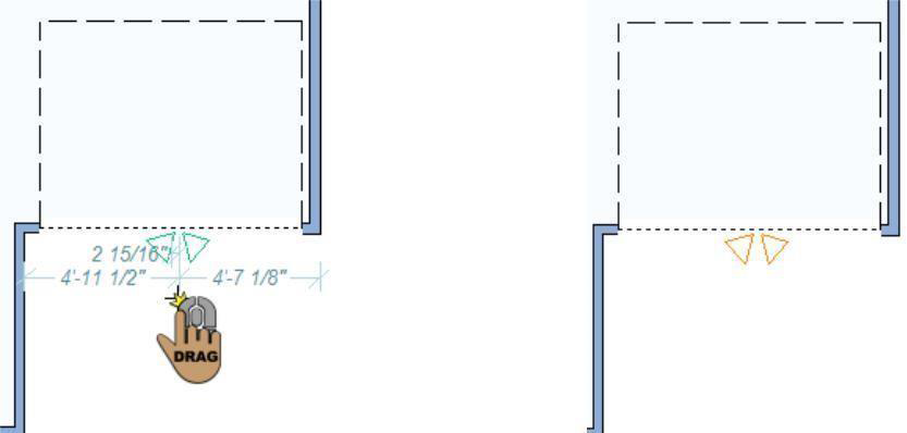
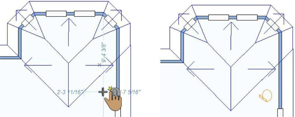
To add a photo beam 
- On the Electrical plan toolbar, click the Photo Beam Tool from the Home Security toolset.
- Use the Click Once to Place drawing method to place the component in your design. In the example below, the photo beam has been rotated to fit into a corner.
To add a security keypad 
-
On the Electrical plan toolbar, click the Security Keypad Tool from the Home Security toolset.
-
Use the Drag Along Wall drawing method to position the component on the side of a wall where you want it and release to place.
To add a security control panel 
-
On the Electrical plan toolbar, click the Security Control Panel Tool from the Home Security toolset.
-
Use the Drag Along Wall drawing method to position the component on the side of a wall where you want it and release to place.
To add a heat detector 
-
On the Electrical plan toolbar, click the Heat Detector Tool from the Home Security toolset.
-
Use the Click Once to Place drawing method to place the component in your design. By default, the heat detector is attached to the ceiling, based on the auto ceiling elevation.
To add a wall-mounted access keypad 
-
On the Electrical plan toolbar, click the Security Access Keypad Wall Mount Tool from the Home Security toolset.
-
Use the Drag Along Wall drawing method to position the component on the side of a wall where you want it and release to place.
To add a pedestal-mounted access keypad 
- On the Electrical plan toolbar, click the Security Access Keypad Pedestal Mount Tool from the Home Security toolset.
- Use the Click Once to Place drawing method to place the component in your design.
Adding Home Automation Components
Automated components can help to make your home simpler and more efficient. There are a number of automation components available in Punch! from network routers to intercoms, and more. These components have default elevations and orientations. For example, the Backup Generator is placed on the ground, however the Backup Generator Panel attaches to a wall at a default elevation. You can reposition any of the home automation components using basic editing techniques.
The home automation components are displayed with dimensions, as you drag along a wall or move the cursor around the design window, which indicate the distance from the center of the component to the nearest wall or other components in the design.
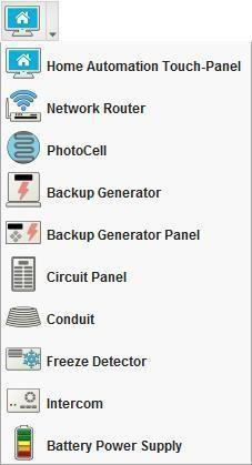
The toolset shown to the right displays the available components in the Home Automation toolset.
Below are some references that may be helpful as you design:
- Rotating a Selection
- Elevating Objects
- Moving a Selection
- AutoSnap and Alignment Options
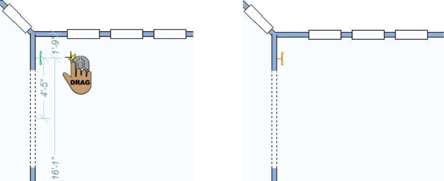
To place a home automation touch-panel 
-
On the Electrical plan toolbar, click the Home Automation Touch-Panel Tool from the Automation toolset.
-
Use the Drag Along Wall drawing method to position the component on the side of a wall where you want it and release to place.
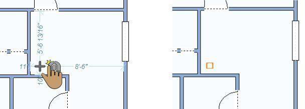
To place a network router 
- On the Electrical plan toolbar, click the Network Router Tool from the Automation toolset.
- Use the Click Once to Place drawing method to place the component in your design.
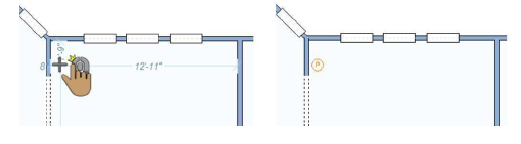
To place Photocell
1- On the Electrical plan toolbar, click the PhotoCell tool fro mthe automation toolset.
2- Use the Click once to place drawing method to place the component in your design.
To place a backup generator
1- On the electrical plan toolbar, click the Backup Generator tool from the automation toolset.
2- Use the Click Once to place drawing method to place the component in your design.
To place a backup generator panel 
-
On the Electrical Plan tab, click the Backup Generator Panel Tool from the Automation toolset.
-
Use the Drag Along Wall drawing method to position the component on the side of a wall where you want it and release to place.
To place a circuit panel
- On the Electrical Plan tab, click the Circuit Panel Tool from the Automation toolset.
- Use the Drag Along Wall drawing method to position the component on the side of a wall where you want it and release to place.
To place a conduit
- On the Electrical Plan tab, click the Conduit Tool from the Automation toolset.
- Use the Click-and-Drag drawing method to set the angle and length for the component. Conduit is visual representation that is displayed in 2D, but not in 3D.
To place a freeze detector
- On the Electrical Plan tab, click the Freeze Detector Tool from the Automation toolset.
- Use the Click Once to Place drawing method to place the component in your design.
To place an intercom 
-
On the Electrical Plan tab, click the Intercom Tool from the Automation toolset.
-
Use the Drag Along Wall drawing method to position the component on the side of a wall where you want it and release to place. The intercom is placed at a default elevation on the wall.
To place a battery power supply 
- On the Electrical Plan tab, click the Battery Power Supply Tool from the Automation toolset.
- Use the Click Once to Place drawing method to place the component in your design.