Transformations
Object transformations are a powerful method for modifying the shape and position of an object. There are eleven tools for transforming objects available through this tool palette. From left to right, across the transformation tool palette they are:

Basic Transforms
- Translate
- Rotate
- Scale/Stretch
- Mirror
- Linear Duplicate
- Polar Duplicate
- Linear array
Advanced Transforms
- Magnet
- Path Duplicate
- Align
- Mate and Connect
- Stretch
- Twist
Translate
The Translate tool is used to move an object from one location to another. Hold the option key to perform a translate copy.
Using the Translate tool
- Click the Translate tool.
- Select the objects to move if not already selected.
- Specify two locations that indicate the start and end movement vector.
- Use the Data Entry Fields to precisely adjust dx, dy, and dz move components.

The move tool will move entire objects or just selected points. In the next example we move only the selected endpoints of a collection of curves.
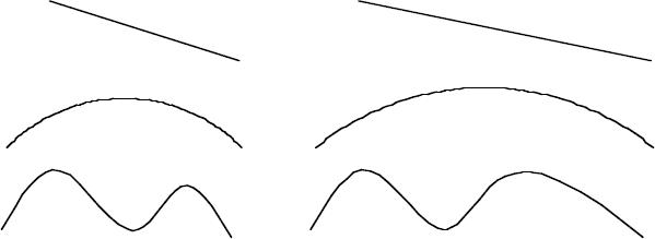
Translate Selected PointsRotate
The Rotate tool changes the angle of an object about an axis. The Rotate command has the following options:
- Rotate about one point
- Rotate between three points
- Hold down the Option key to copy
Rotate One Point
The Rotate One Point option rotates selected objects about a user supplied origin and angle. The default axis of rotation is the construction plane normal. Select the pull-down menu in the prompt line to choose an alternate rotation axis.
Using the Rotate One Point tool
- Select objects to rotate if not already selected.
- Pick the axis to rotate about if not the work plane.
- Type in the rotation angle in the Data Entry Window.
- Click a point which is the rotation origin.
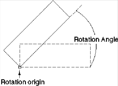
Press and hold the Option key (Alt key) if you would like to perform a rotate copy.
Rotate Three Points
The Rotate Three Points command rotates an object by three points specified by the user. The first point defines the center of rotation, the second is the from point, and third point is the rotate to point. Internally, a transformation matrix is created that rotates the object an angle defined by the three points.
Using the Rotate Three Points tool
- Select objects to rotate if not already selected.
- Click a point that is the rotation center.
- Click a point that is the rotation from point.
- Click a point that is the rotation to point.
- The Data Entry Fields fills the angular value for the three points. Use the Data Entry Fields to change to a different value if needed.
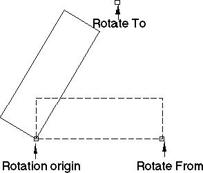
Press and hold the Option key (Alt key) if you would like to perform a rotate copy.
Scale
The Scale command provides options to enlarge or shrink an object. The user interface provides two types of scaling: uniform and differential. Uniform scaling provides the same scale factor to the x, y, and z components. Differential (or non-uniform) scaling can scale each axis with a different value. Use the pull-down menu to select uniform or differential scaling.
Uniform Scale
The Uniform Scale tool will scale using input from mouse clicks or a scale value entered in the Data Entry Window. The following two examples show how to accomplish uniform scaling.
Using the Uniform Scale with Data Entry Window
- Select objects to rotate if not already selected.
- Click an anchor point for the scale operation. This represents the scale origin and stays fixed throughout the scaling operation.
- Click a reference point for the scale magnitude.
- Click an ending point for the scale magnitude.
From the above mouse clicks, the scale origin is the first click and the scale value is the distance as Scale
(endpoint - Anchor Point) / (Reference Point - Anchor Point). The mouse click method supports both shrinking and stretch of curves, surfaces, and solids. Press the option key to perform a scale copy.
Using the Uniform Scale with Data Entry Window
- Select objects to rotate if not already selected.
- Click an anchor point for the scale operation. This represents the scale origin and stays fixed hroughout the scaling operation.
- Type in a scale value using the Data Entry Fields and hit Enter on the keyboard.
Differential Scale
The Differential Scale tool will expand or shrink a curve, surface or solid, in a non-uniform manner with respect to the x, y or z axis. The following example shows how to accomplish differential scaling.
Using the Differential Scale tool
- Select objects to rotate if not already selected.
- Use the Data Entry Fields to specify the x, y, and z scale components.
- Click an anchor point for the scale operation. This represents the scale origin.
- Hold the option key to perform a copy.
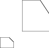
Differential Scale Copy (x=2, y=3)
Mirror
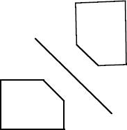
The Mirror command produces a mirror image of objects through a mirror plane. A mirror plane is defined by one of the primary axes (x, y, z) or a user-defined vector. Use the pull down in the message line to specify the plane or axis.
Using the Mirror 2 Pts tool
- Select objects to rotate if not already selected.
- Select the 2 Pts Option from the Prompt pull down.
- Click beginning point for mirror reference line.
- Click ending point for mirror reference line.
- Hold down the Option key to perform a mirror copy.
Linked Mirror
The Linked Mirror tool creates an associative, mirrored copy of one or more objects so when the original (parent) object is edited or moved, the associative (child) object will as well.
Linear Duplicate
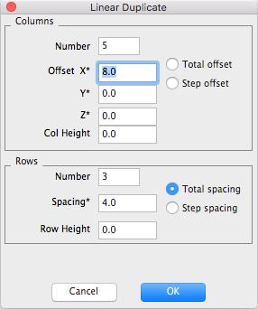
The Linear Duplicate tool creates copies of an object based on specifying rows, columns, and spacings. The Linear Duplicate tool can be used to create an array of 2D or 3D objects. Columns are the vertical series in an array whereas rows are the horizontal series. The command displays the dialog box below to gather information related to columns, rows, and spacing.
Column Information
Number per Row Specifies the total number of columns of objects. This includes the selected object.
Offset X, Y, Z The horizontal x, y, and z distances associated with the combinedcolumns or individual column offsets. The asterisk indicates that these fields can be filled in from the Snap tool by referencing data in the drawing.
Col. Height
The distance between the start of each column, creating a vertical ascent or decent.
Total Offset
A radio button indicating the Offset XYZ values correspond tothe combined columns.
Step Offset
A radio button indicating the Offset XYZ values correspond tothe individual column offsets.
Row Information
Number of rows
Specifies the total number of rows.
Spacing
The vertical spacing between rows
Row Height
The distance between the start of each row, creating an indented formation.
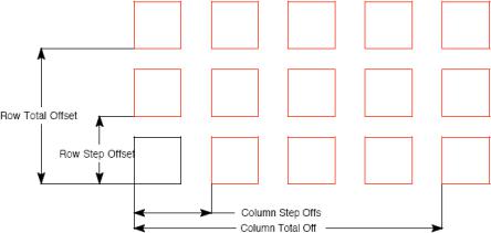
Linear Duplicate Settings
Using the Linear Duplicate tool
- Select objects to duplicate if not already selected.
- Specify the row, column, and spacing information in the linear duplicate dialog box.
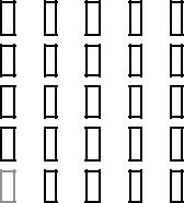
5x5 Linear Duplicate
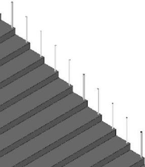
3D linear duplicate

Polar Duplicate
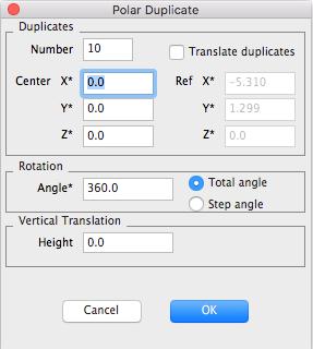
The Polar Duplicate tool creates multiple copies of objects arranged in a uniform circular pattern. The Polar Duplicate tool can be used to create an array of 2D or 3D objects.
Duplicates Information
Number Specifies the number of rotational copies. This includes the selectedobject.
Center X, Y, Z The center of the polar array. The asterisk indicates that these fields can be filled in from the Snap tool.
Ref X, Y, Z The reference point when translate duplicates is checked. This point serves as the origin for the object rotated.
Translate duplicates A checkbox indicating that the objects are only translated into the polar position.
Rotation Information If not checked, the objects are rotated at each duplicated position.
Angle Specifies the polar angle.
Total Angle A radio box indicating the angle is the total polar angle.
Step Angle A radio box indicating the angle is the individual angle betweensuccessful polar increments.
Vertical Translation Height If the array is to ascend vertically, the Height specifies the vertical distance between each object in the array.
Associative Duplicates Creates a parent/child relationship between the original object and the duplicates. When selected, the duplicates model the changes made to the original object. When this object is not selected, each duplicate can be edited individually. (Available for 3D duplicate).
Using the Polar Duplicate tool
- Select objects to rotate if not already selected.
- Specify the number, center, and angle information in the polar duplicate dialog box.
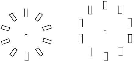
Rotated Translated Polar Array
Linear Array
This tool creates and distributes copies based on the starting reference point and cursor location. As you move your cursor, the angle and number of copies increases or decreases. The spacing value describes the absolute distance between each consecutive object.
Using the Linear Array tool
- Select the object you want create an array with.
- Click the Linear Array tool.
- Click to select the starting point for the array.
- (optional) Enter a value in the Spacing text field, on the Data Entry window. Press the Enter key.
- Drag your cursor in the direction you want the linear array. As you drag your cursor the array increases or decreases in size, depending on which way you’re dragging.
- Click to set the end of the array.

Magnet
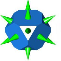
The new Magnet Tool is used to quickly snap one part to another. The part is moved from its current location, orientated, and centered within the selected face. This tool works with other objects besides solids. i.e. you can place a curve profile on a face. Magnet is not associative.
Path Duplicate
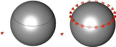
This tool creates copies of an object along a curve (line, spline, arc, circle or ellipse). The tool also has the ability to reference surface normals, aligning the selected object with the normals of a surface.
Using the Path Duplicate tool
- Select objects to rotate if not already selected.
- Click origin point for the objects you want to translate along path. This point will move to the path start (1 in the figure below).
- Click two points defining an alignment vector. This vector defines the alignment to the slope path
(2 and 3 in the figure below).
Referencing surface normals
- Press and hold the Ctrl key (Option for Mac) to enable the path translation.
- Click the translation path for the object.
- Click the copy origin. The location from the selected body will be translated to a location along the path.
- Select two points for the alignment axis. The axis will be aligned with the surface normal calculated from the location on the path.
- Select the body for normals alignment. The surface normals will be calculated from this referenced body, which can be a surface or solid.

Align
The Align tools provide options for positioning objects relative to other objects by:
- Left & Right sides
- Centers
- Tops & Bottoms
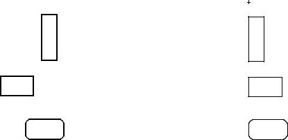
Align Left Sides
The Align Left Sides option will move selected objects such that their left extents are aligned
Align Right Sides
The Align Right Sides option will move selected objects such that their right extents are aligned.
Align Tops
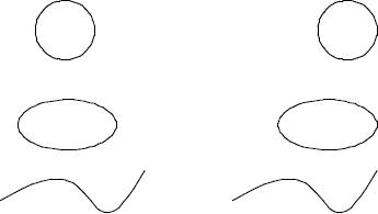
The Align Tops option will move selected objects such that their top extents are aligned.

Align Bottoms
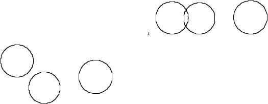
The Align Bottoms option will move selected objects such that their bottom extents are aligned
Circles
Circles
Before Align
After Align
Align Bottom
Align Centers Horizontal
The Align Center Horizontal option will move selected objects such that the center of their bounding extents is aligned.

Align Centers Vertical
The Align Center Vertical option will move selected objects such that the center of their bounding extents is aligned.

Align Grid
The Align Grid option will move selected objects such that the lower left of their bounding extents is at a grid node.
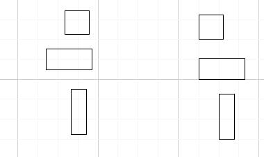
Align Spaced Vertical
The Align Spaced Vertical option will move selected objects such that the vertical bounding box spacing is even between the objects.
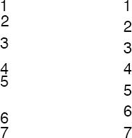
Align Spaced Horizontal
The Align Spaced Horizontal option will move selected objects such that the horizontal bounding box spacing is even between the objects.

Mate and Connect
The Mate and Connect tools provide options for positioning and aligning faces of parts relative to other faces by:
- Connect Point
- Mate Faces
- Align Faces
- Insert Faces
Connection
The Connection tool will move a part to another part, connecting two points between the parts. The Connection is associative; moving the parent part will move the other to maintain the connection.
Using the Connection tool
- Select the Connect tool from the Advanced Transforms tool palette.
- Select the face to move.
- Select the connection point on the face to move from.
- Select the face to move to (parent part).
- Select the connection point on the face to move to.
Mate Faces
The Mate Face tool will rotate a selected planar face such that the face normal is exactly the opposite as the referenced face. The Mate Faces tool is associative; moving one part will move the other to maintain the mated faces.
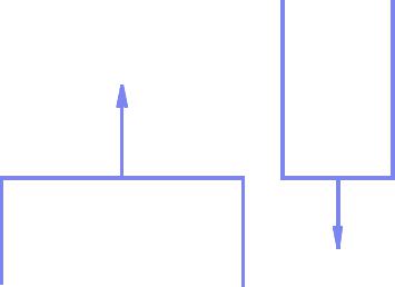
Mate Face Resulting Orientation
Using the Mate Face tool
- Select the Mate Face tool from the Advanced Transforms tool palette.
- Select the planar face to align.
- Select the planar face to align to.
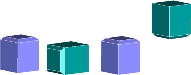
Align Tool
Align Faces
The Align Faces tool will rotate a selected planar face such that the face normal is exactly the same as the referenced face. Align will also allow selection of cylinder faces in which case the axis will be aligned to each other. The Align Faces tool is associative; moving one part will move the other to maintain the aligned faces.
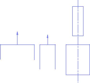
PlanarCylinder
Using the Align Face tool
- Select the Align Face tool from the Advanced Transforms tool palette.
- Select the face to align (planar or cylindrical).
- Select the face to align to (same face type as above).
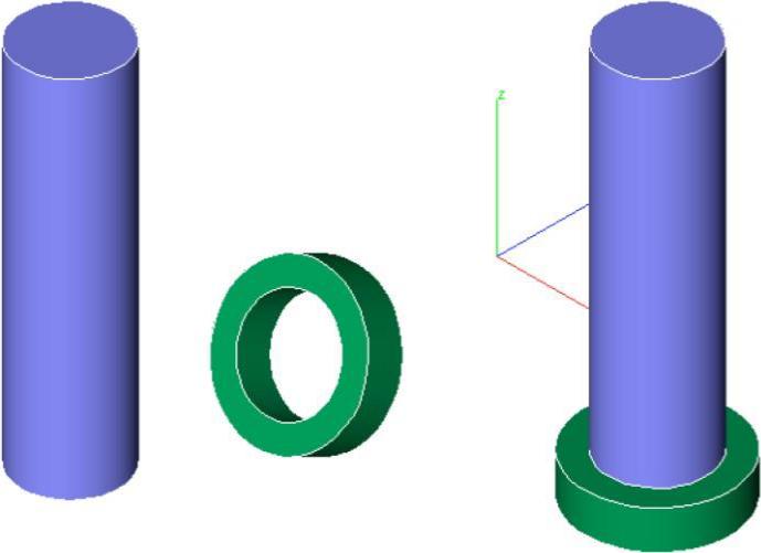

Planar Face Align
Insert Face
The Insert Face tool will move and align cylindrical faces. Typically, this is used to insert a bolt type shape into a hole type shape. The Insert Face tool is associative, moving the hole shape will automatically update and move the inserted face.
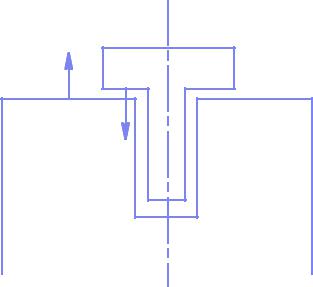
Insert Face Resulting Orientation
Using the Insert Face tool
- Select the Insert Face tool from the Advanced Transforms tool palette.
- Select the face to align (planar or cylindrical).
- Select the face to align with (same face type as above).
- Select the face to mate.
- Select the face to mate with.
If the first face you select is cylindrical, the second alignment face must also be cylindrical. In the case of cylindrical faces, the axes of the cylinders are aligned
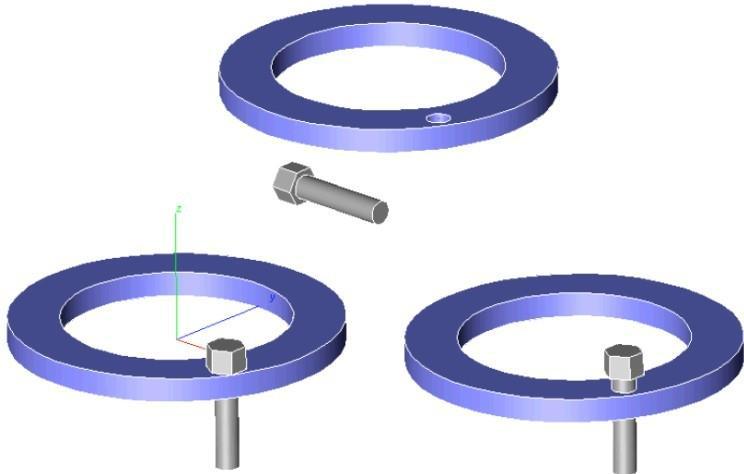
Insert Face Examples

Stretch
The Stretch tool is used to stretch curves, surfaces, and solids. Stretching is a non-uniform scaling operation along a stretch axis.
The stretch axis is defined by two points specified by the user. The material to be stretched is bounded by planes perpendicular to the stretch axis at the two supplied points. The third point defines how much the body is stretched. The distance from the third point to the second point defines the distance stretched.
Using the Stretch tool
- Select the Stretch tool from the advanced transformations tool palette.
- Specify the start and end regions for stretching
- Specify the stretch to point. Material is stretched from the second point to this stretch point.
- To stretch the entire body, specify two points that lie outside the body.

Global Stretch of a Sphere
The Stretch tool can also be used to stretch regions within a body. To perform a local stretch, specify one or both points within the body.

Local Stretch Example
Note: Local stretching introduces new faces and edges at the stretch start or end region. Continuity at thenew edges is positional only.
Twist
The Twist command is a warp class tool that will apply an angular twist to a curve, surface or solid. Use the Twist tool to warp a simple body into a shape not achievable with normal parametric modeling methods. Note you can twist a curve, surface or solid.
Using the Twist tool
- Select the Twist tool from the advanced transform tool palette.
- Specify the twist angle in the data entry window.
- Specify the start point for the twist region.
Specify the endpoint for the twist region.
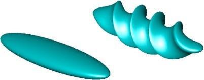
Global Twist Example
The start and endpoints specify the axis for the twist. Perpendicular to the axis start and endpoints are two planes defining the volume of material impacted by the twist operation. If the two points lie within the body, a localized twist operation occurs.
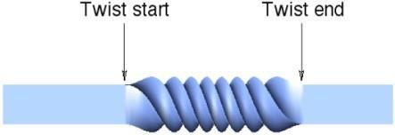
Local Twist Example
Magnet Snap
The Snap command is a single tool that will translate and orientate a part onto another part. . Using the Snap tool
- Select the Snap tool from the advanced transform tool palette.
- Pick entities or solid face to snap from.
- Pick solid face to snap entities or solid to.
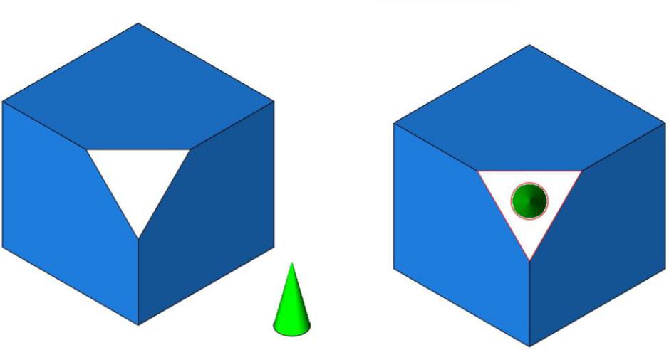
Note the Snap tool will translate the face center of one object to the other.