Paper Size
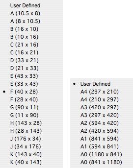
Selecting from this drop-down list sets the Width and Height fields according to standard drawing sizes. The list of standard drawing sizes (ANSI or ISO) corresponds to the current unit of measure. Set the unit of measure in the preferences.

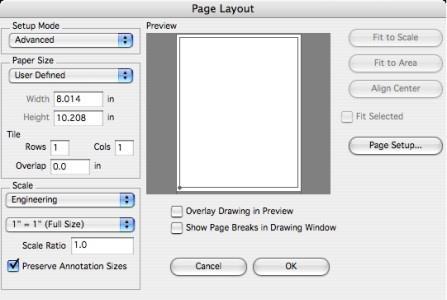
Width
Sets the drawing width using the current unit of measure.
Height
Sets the drawing height using the current unit of measure.
Rows and Columns Mode
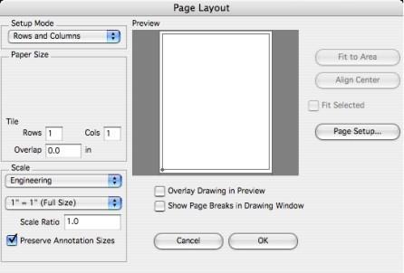
In this mode, printing is targeted to a user-defined, arbitrary drawing size. The number of tile rows and columns specify the drawing size. The drawing size is not limited to the physical paper size in your printer. The tiles are indicated in the preview by the lighter matrix of lines within the drawing border. In this mode it is not possible to have “excess” paper in the drawing. Setting the tile rows and columns to 1 x 1 with Overlap set to 0 is equivalent to single page mode.

Rows
Sets the drawing height as the number of tile rows.
Cols
Sets the drawing width as the number of tile columns.
Overlap
Sets the amount of overlap (using the current unit of measure) included along the top and right edges of each tile page. The overlap provides a duplicate printed region on each tile page that can be used for tile alignment, gluing or taping. This value may be set to 0.
Advanced Mode
In this mode, printing is targeted to a user-defined, arbitrary drawing size. The drawing size can be specified as a combination of Height and Width and/or Rows and Columns. The drawing size is not limited to the physical paper size in your printer. The tiles are indicated in the preview by the lighter matrix of lines within the drawing border. The lighter tile matrix lines extending past the drawing border indicate the presence of excess paper.
The dominant drawing size values are indicated in the dialog box by the bold labels. For example, the dialog below shows that the drawing width is 36 in and the drawing height is 3 Tile Rows. The dimmed labels indicate the corresponding reference sizes. That is, the Width of 36 in corresponds to 5 Tile Columns and the height of 3 Rows corresponds to a Height of 30.875in.

In addition to the drawing size settings that vary according to the setup mode, there are additional settings that are common to all modes. These are detailed below:
Setting the Drawing Scale
You may set the print scale using either the drop-down list of common values or you can enter an arbitrary value in the Scale Ratio field.
Fit to Scale (Advanced mode only)
The drawing size Width and Height will be adjusted to fit the geometry at the current Scale value.
Fit to Area
The Scale value will be adjusted to fit the current drawing size Width and Height.
Align Center
Centers the drawing border to the geometry extents.
Fit Selected
If checked, only the selected objects will be considered when making the Fit to Scale, Fit to Area, and Align Center adjustments.
Overlay Drawing in Preview
If checked, the actual drawing geometry will be displayed in the preview section. For very large drawings this may be too slow. If not checked, bounding rectangles are drawn in place of each drawing object.
Show Page Breaks in Drawing Window
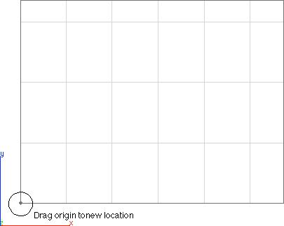
If checked, the drawing border and any tile matrix lines are drawn to the drawing window. This is necessary if you need to move the drawing border. You may move the origin of the drawing border by positioning the pointer over the lower left corner of the border in the drawing window, pressing the mouse button, and dragging to new location.
