Workplanes
(Available in XT Pro)
Default UI Menu: Tools/New UCS
Ribbon UI Menu:

A workplane is the plane on which 2D objects are created within the the current coordinate system (UCS or WCS), and on which most 3D objects are based. In 2D, you always work on the same workplane - the XY plane of the current UCS. In 3D, however, the workplane may change frequently.
In 3D, the workplane is still in the XY plane by default. But if you have 3D objects in your model, you can temporarily move the workplane to the facet where your cursor is. This is set in the Drawing Aids window, which can be opened by right-clicking on the SNAP or GEO field at the bottom of the screen.
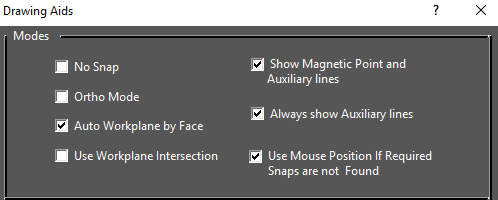
Note: For details on Drawing Aids, see Snap Settings
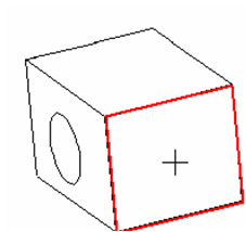
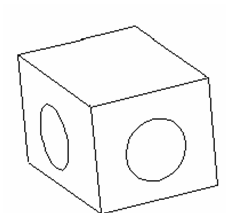
When Auto Workplane by Face* is checked, the facet will highlight in red when the cursor passes over it.
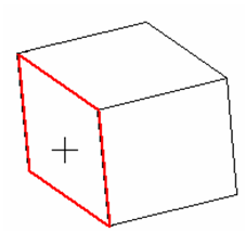
The object you draw will be placed on that facet.
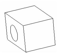
The facet workplane is temporary; after the object is created, the workplane returns to the XY plane. If you highlight another facet, that workplane will be temporarily active for the next object you create.
Note: If you create an object with no facet highlighted, the default workplane will be used.
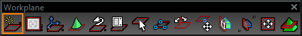
If you uncheck Auto Workplane by Face in Drawing Aids, the workplane will always be the default workplane. If you don't want to use the XY plane of the current UCS, you can use one of the Workplane commands. These commands can be found on the flyout toolbar on the main toolbar.
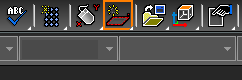
You can also display the Workplane toolbar by right-clicking in any toolbar area and selecting Workplane.
Note: The Design Director also contains tools for manipulating workplanes, creating workplanes, and displaying the view according to a selected workplane. See Design Director-Workplanes
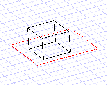
If you are working with the grid turned on (see [Grid], the grid will lie on the current workplane.
Changing the Workplane
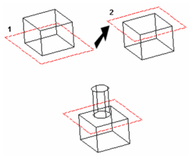
While working in 3D, you will probably have to change the workplane frequently to create objects that have the correct location and orientation.
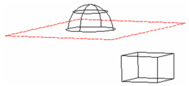
For example, create a cube based on the default workplane. If you want to create a cylinder on the top face of the cube, you must move the workplane up to this face. Then you can place the cylinder in the correct location.
The workplane can also change when you select objects, depending on whether the 2D or 3D Selector is used. See 2D-3D Selector
Workplane by View

Default UI Menu: Tools/New UCS/By View
Ribbon UI Menu:

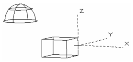
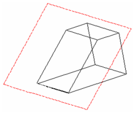
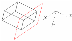
Sets the workplane according to the current view.
- Position the model to the desired view. In this example, the current workplane is By World.
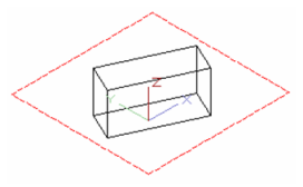
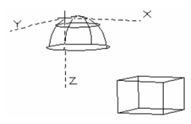
- Select By View. The workplane is turned so that it is parallel to the view plane. The Z axis becomes perpendicular to the drawing screen.
Workplane by World

Default UI Menu: Tools/New UCS/By World
Ribbon UI Menu:

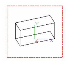
Sets the workplane based on the WCS (World Coordinate System).
Note: By World is the default workplane when selecting objects that reside on different workplanes.
You can display the WCS at the lower left corner of the screen by opening the Preferences and checking Show World CS.
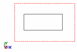
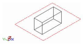
By World, top view
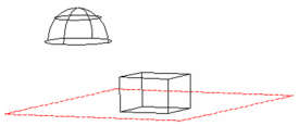
By World, Isometric_SW view
Workplane by Entity

Default UI Menu: Tools/New UCS/By Entity
Ribbon UI Menu:

Sets the workplane according to the coordinate system of a selected object, block, or group.
- Click By Entity, and the cursor becomes a dashed representation of the current UCS. Click the desired object.
The workplane is placed along the plane on which the object was created.
- To change the workplane to another object, use the tool again. Click the desired object.
The workplane is positioned according to the selected object.
Tip: If an object is listed in the Graphics section of the Design Director, you can set the view to an object's Workplane by Entity, and set this workplane as the current workplane.
Workplane by 3 Points

Default UI Menu: Tools/New UCS/By 3 Points
Ribbon UI Menu:

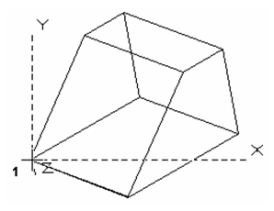
Sets the workplane to fit three points. You can select these points, or enter their coordinates in the Coordinate Fields.
- Select the UCS origin.
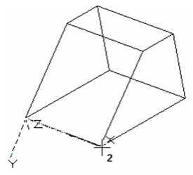
- Select the second point to define the +X direction.
- Select any point that lies on the desired X-Y plane.
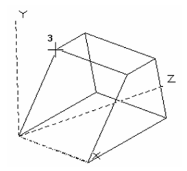
The workplane is created.
Workplane Origin

Default UI Menu: Tools/New UCS/Origin
Ribbon UI Menu:

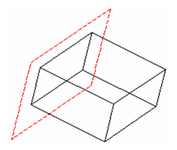
Sets the workplane parallel to (offset from) the current workplane, by relocating the UCS origin.
- When you select UCS Origin, the cursor becomes a set of dashed axes, with the X-Y plane parallel to the current X-Y workplane.
- Select a new UCS origin, or enter the coordinates in the Coordinate Fields.
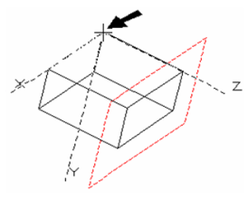
The parallel workplane is created.
Fit to Window
Default UI Menu: Tools/New UCS/Fit To Window
Ribbon UI Menu:

Fits the workplane rectangle to the current window. This is useful after a view change such as zoom or pan.
Place on WorkPlane
Default UI Menu: Modify/Place on Workplane
Ribbon UI Menu:
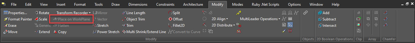
Enables you to place 2D objects on the current workplane.
- Select the objects you want to move.
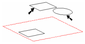
- Select Modify / Place on Workplane. The objects are moved onto the current workplane.
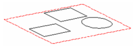
This tool can be useful, for example, for objects that have been selected with the 3D Selector and moved from their original workplane. If you try using a 2D tool like Fillet on two lines that sit on different workplanes, the tool will not work; one of the lines must be moved to the workplane of the other.
Saving and Recalling WorkPlanes

Previous
 Recalls the previous workplane. Using this tool repeatedly will toggle between the current and previous workplanes; it will not scroll back through several workplanes.