Program setup
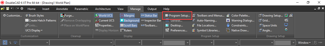
Program Setup
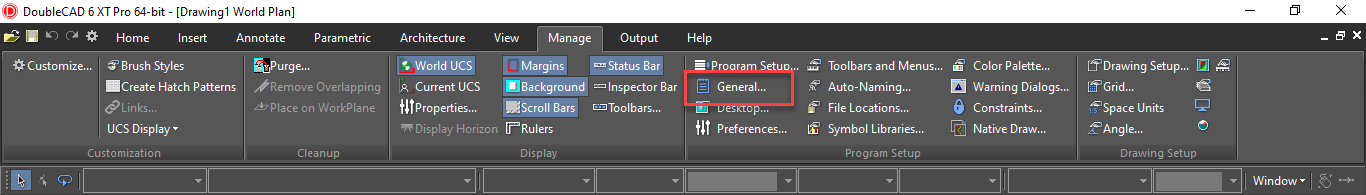
Default UI Menu: Options/Program Setup
 Ribbon UI Menu:
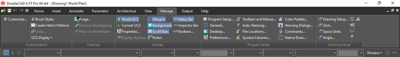
Contains pages in which you can control DoubleCad program settings. You can access each page directly from the Options menu. The options that you set in this window are saved when you exit DoubleCAD and will remain in effect the next time you start the program. The Program Setup pages can be accessed from the Options menu.
You can also display the Program Setup toolbar by right-clicking in any toolbar area and selecting Program Setup.
Tip: You can also use the System Defaults in the DC Explorer Palette to set program setup options.
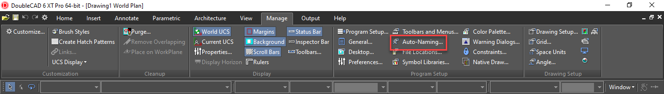
Auto-Naming
Default UI Menu: Options/Program Setup/Auto-Naming
Ribbon UI Menu:
Controls how groups, blocks, and symbols are named. See Auto-Naming of Groups, Blocks,
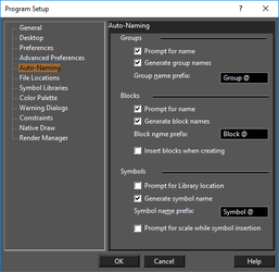
Prompt for name: You will receive a prompt each time a new item is created. Generate names: Names will be automatically assigned. Prefix: If names are automatically generated, you can enter a string that appears before the item name. The "@" character is a placeholder for the automatic number. Insert blocks when creating: Each block will be inserted into the drawing once it is created. Prompt for library location: If not checked, all saved symbols will be stored in the default folder. See Loading Symbol Folders into the Library
Note: If you turn off both the Prompt for name and Generate names options, names will not be assigned to groups.However,names will be assigned to blocks and symbols.
Color Palette
Default UI Menu: Options/Program Setup/Color Palette
Ribbon UI Menu:
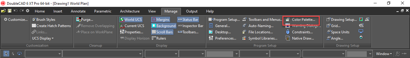
Enables you to add, modify, or delete colors from the DoubleCAD palette.
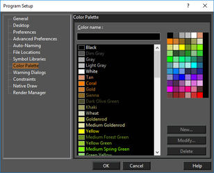
To add a new color, type the name and click New. You will then be prompted to select a color from the color wheel. You can modify a color by selecting it from the list and clicking Modify. Delete a color by selecting it and clicking Delete. When you have the colors you want, they can be displayed for easy selection in the Colors and Brushes palette. See Colors and Brushes
The Color Wheel
You can set colors by RGB values, or by Hue, Saturation, and Value numbers. Red, Green, Blue: Sets the amount of each color in the light. Values can be a maximum of 255. Hue: The color value, where 0 is red, 60 is yellow, 120 is green, 180 is cyan, 200 is magenta, and 240 is blue. If you change the hue, the values for red, green, and blue will be changed to match. Sat: The saturation level for the color (amount of color), up to a maximum of 240. Lum: The luminosity (brightness) of the color.
Constraints
Default UI Menu: Options/Program Setup/Constraints
Ribbon UI Menu:
Settings and controls for geometric and dimensional constraints.
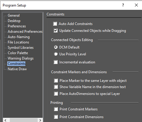
Auto Add Constraints: If checked, the Auto Add Constraints tool is enabled. Any constrainable geometry you create while this is active will have constraint automatically assigned.
Update Connected Objects while Dragging: Dynamically updates the position, shape, and size of constrained objects as you drag them within the Edit tool.
Connected Objects Editing:
DCM Default: Changes to any part of a set of constrained objects can affect all objects equally.
Use Priority Level: Constraint changes to any part of a set of objects will affect that part first, with minimal changes to the remaining objects.
Incremental Evaluation: Constraint changes are constantly checked and changes are being made. If disabled, the results will be checked only after changes are made. For large scale changes, this option should be enabled.
Constraint Markers and Dimensions
Place marker to the same layer with object: Constraint markers are placed on the same layer as the object that is constrained. Otherwise, they are placed on their own layer. Show variable name in dimension text: Displays the variable name in parentheses after the dimension value. Printing: Choose whether constraint markers and constrained dimensions will be included when printing.
Desktop
Default UI Menu: Options/Program Setup/Desktop
Ribbon UI Menu:
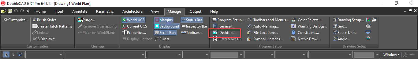
Controls what appears on the screen.
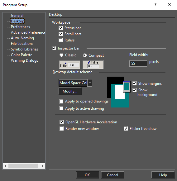
Workspace: Controls the display of the working area Status Bar: Displays or hides the Status Bar. Scroll bars: Displays or hides the scroll bars. Rulers: Displays or hides the rulers.
Inspector Bar
Inspector Bar: Displays or hides the Inspector Bar. See Inspector Bar Classic: Set Inspector bar fields and labels to be in the classic side by side orientation, Compact: Set Inspector bar fields and labels to be in the compact over/under orientation, Field width: Specify the field width.
Desktop default scheme
Desktop Scheme: Customizes the color of paper and background, and floating palettes. Click Modify to change an element's color.
Tip: You can also click the different elements in the preview window.
Show margins: Displays page (printer) margins. Show background: If checked, the background behind the paper will be displayed. If unchecked, the background will be white. Apply to opened drawings: Apply changes in the scheme to all opened drawings. Apply to active drawing: Apply changes to the currently active drawing.
Tip: You can switch off the paper until you're ready to print, then use the Page Setup (see Page Setup to place your drawing on the page.
OpenGL Hardware Acceleration: Available if your video card is equipped with an accelerator, take this characteristic into account while performing a render. Render new window: When you render your drawing, the render view will open in a new drawing window. Background Render: With this option, DoubleCAD tools work faster in Render mode; rendering will "interfere" less with other tools. This setting can only be applied when working with one window.
File Locations
Default UI Menu: Options/Program Setup/File Locations
Ribbon UI Menu:
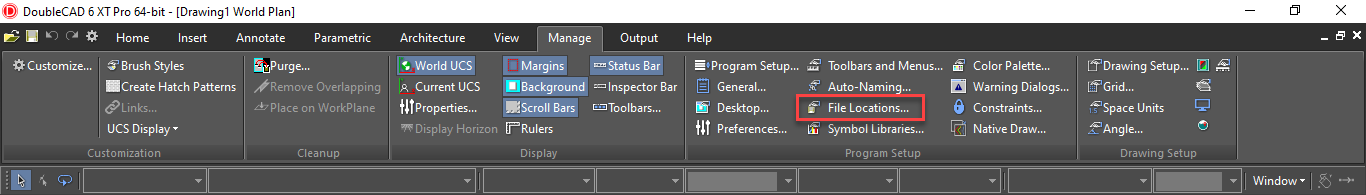
Enables you to specify the folders where DoubleCAD places several types of program files.
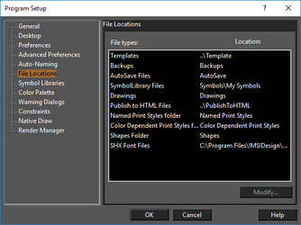
Templates (.2ct) - Files in which you save settings as well as block libraries, symbol libraries, and scripts, that you can use to start a new drawing. Backups (.bak) - Backups that are created if you check Make Backup Copies option in the General page. AutoSave Files (.asv) - Files that are saved automatically, if this option is turned on in the General page. These files allow you to restore work after a system crash. Symbol Library Files (.slw) - Sets of related symbols, saved to one common .slw file or a set of drawing files saved to a specified folder. Drawings (.tcw) - Drawings and models you create in DoubleCAD. Publish to HTML Files - Files created using File / Publish to HTML. Print Styles: See Print Style Options Shapes (.shx): Shape files (.shx) used in the creating of line styles. (This is not the same as *.shx font files.) See Line Styles
Tip: If you have two disk drives (or access to a network drive), it is wise to have your backup files automatically saved to a second drive.
General Setup
Default UI Menu: Options/Program Setup/General
Ribbon UI Menu:
Sets file opening and saving parameters, as well as user information
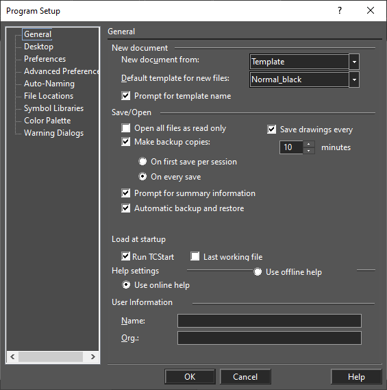 New document from: Select how files will be opened when using File / New.
Default template for new files: If no template is specified when creating a file, a default template will be used. This option sets the default template.
Prompt for template name: You will be prompted for a template each time you start a new file. If you want to use the default template without being prompted, clear this box.
Open all files as read-only: If checked, files cannot be edited.
Make backup copies: If checked, select On First Save or On Every Save to determine how often backups will be made. Backup files have the extension .bak. By default, backup files are saved in the same folder as your primary drawing files, but you can change this on the File Locations page.
Save drawings every: If checked, autosave copies (.asv files) will be made at the specified intervals. After a system crash, DoubleCAD will open the autosave version of your drawing as soon as you launch DoubleCAD. Autosave files are stored in the AutoSave folder by default, but you can change this on the File Locations page.
Prompt for summary information: The Summary Information window enables you to record user information connected to your drawing. If checked, this window will be displayed the first time that you save any drawing to disk, and whenever you use Save As to save a new copy of the file.
Save desktop on exit: If checked, the desktop settings (toolbars, etc.) will be saved when you exit the program.
Load at startup: You can choose to load the last working file and the last window layout see [Multiple Windows of the Same File each time you start DoubleCAD.
Help Settings: Specifies how help will be accessed.
User Information: Basic user information
New document from: Select how files will be opened when using File / New.
Default template for new files: If no template is specified when creating a file, a default template will be used. This option sets the default template.
Prompt for template name: You will be prompted for a template each time you start a new file. If you want to use the default template without being prompted, clear this box.
Open all files as read-only: If checked, files cannot be edited.
Make backup copies: If checked, select On First Save or On Every Save to determine how often backups will be made. Backup files have the extension .bak. By default, backup files are saved in the same folder as your primary drawing files, but you can change this on the File Locations page.
Save drawings every: If checked, autosave copies (.asv files) will be made at the specified intervals. After a system crash, DoubleCAD will open the autosave version of your drawing as soon as you launch DoubleCAD. Autosave files are stored in the AutoSave folder by default, but you can change this on the File Locations page.
Prompt for summary information: The Summary Information window enables you to record user information connected to your drawing. If checked, this window will be displayed the first time that you save any drawing to disk, and whenever you use Save As to save a new copy of the file.
Save desktop on exit: If checked, the desktop settings (toolbars, etc.) will be saved when you exit the program.
Load at startup: You can choose to load the last working file and the last window layout see [Multiple Windows of the Same File each time you start DoubleCAD.
Help Settings: Specifies how help will be accessed.
User Information: Basic user information
Preferences
Default UI Menu: Options/Program Setup/Preferences
Ribbon UI Menu:
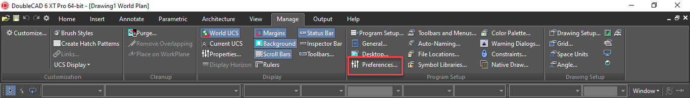 General program options, such as cursor shape, axis color, zoom factor, and display of coordinate system icons.
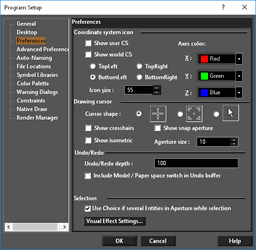
Coordinate system icon:
You can choose to display the User CS and/or World CS symbol/s.
For both, you can set the color of the axes and size of the icon.
For the World CS, select the corner of the screen where it will be displayed: TopLeft, TopRight, BottomLeft, BottomRight
Drawing cursor
Cursor Shape: Select one of the three shapes provided.
Show crosshairs: Overrides the normal cursor, displaying a screenwide horizontal and vertical line intersecting at the cursor position.
Show Isometric: Overrides the normal cursor, displaying all three axes.
Show Snap Aperture: Displays a circular area around the cursor whose radius is the Aperture Size. Aperture is used while snapping, to detect objects.
Aperture size: Specify the radius of the aperture in pixels.
You can also use the View | Display | Cursor menu to change the cursor display.
Undo/Redo
Undo/Redo depth: Sets the number of operations stored in the Undo buffer.
Include Model / Paper space switch in Undo buffer: If checked, switching between Model and Paper spaces will be included in the Undo buffer.
Selection
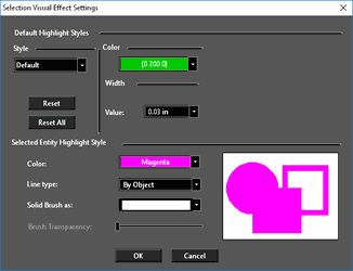
Use Choice if several entities in aperture while selection: If more than one object lies within the aperture area during a selection, a small window appears from which you can select the desired object.
Visual Effect Settings: Settings for the various "highlighting" methods. See Selection Visual Effects Settings.
Symbol Libraries
Default UI Menu: Options/Program Setup/Symbol Libraries
Ribbon UI Menu:
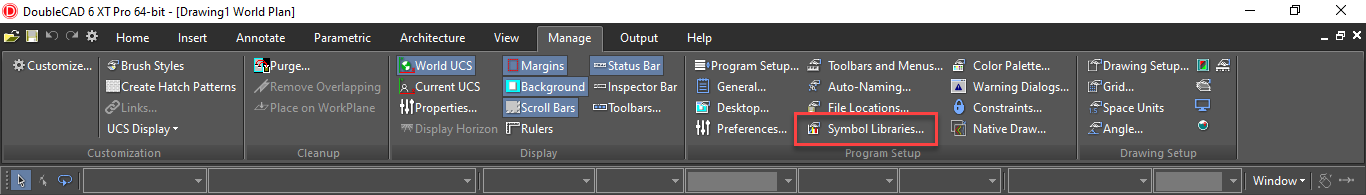
Displays the folders containing files that can be viewed in the Library palette.
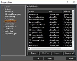
Click New to add more folders. You can also modify the name of a library folder or file, or delete or modify symbol library files and/or folders. You can also access the symbol libraries from the Library palette. See Library
Toolbars and Menu
Default UI Menu: Options/Toolbars and Menus
Ribbon UI Menu:
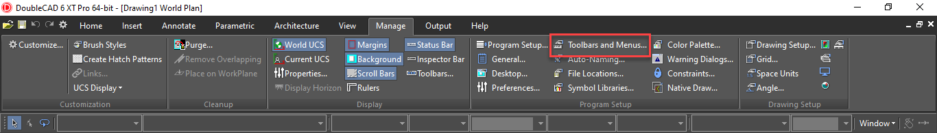
Open the Customize window to the Toolbars page to modify toolbars. See Customize Toolbars
Warning Dialogs
Default UI Menu: Options/Program Setup/Warning Dialogs
Ribbon UI Menu:
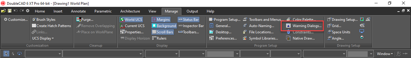
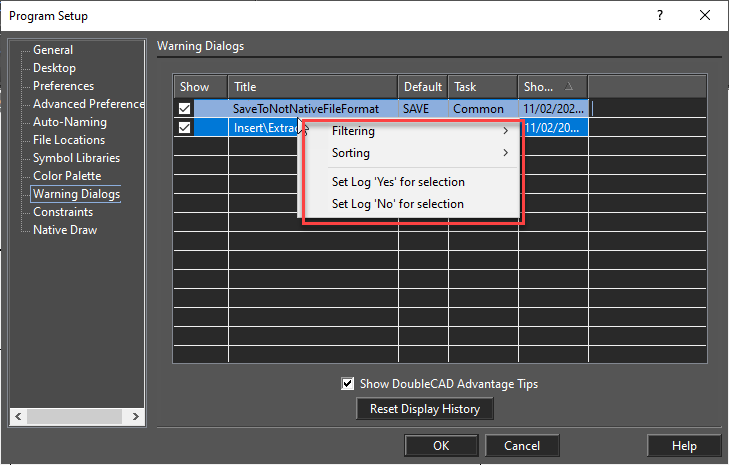
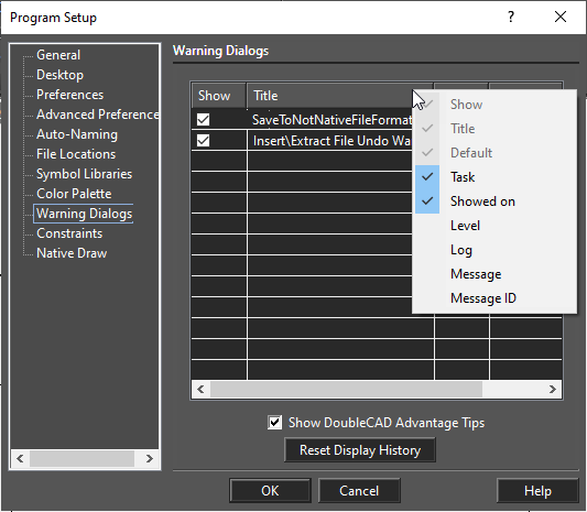
Controls the display of DoubleCAD warning messages. If you received a warning message with the "Don't show this message again" checkbox, the warning message will appear in this table. Use the Show column to show or hide messages.UI enhancements of the Warning dialogs page Show/hide list columns. Right click on the header of the list to open the local menu. This makes it possible to show/hide list columns. NOTE: The first three columns are always visible.
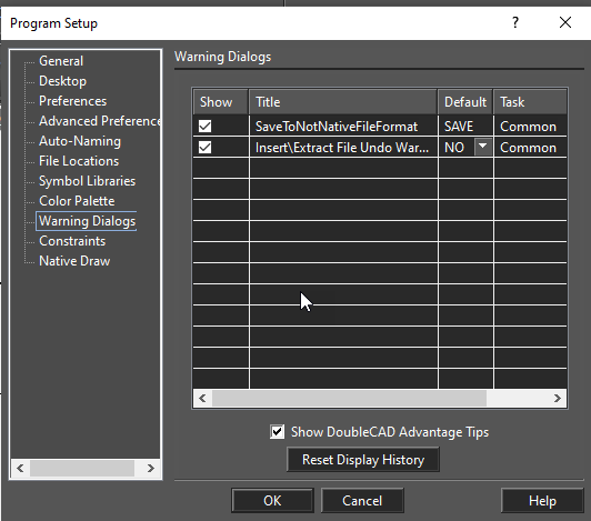
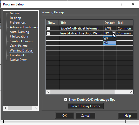
 Setting the value in the 'Default' and 'Log' columns
Left clicking in a cell in the 'Default' or 'Log' column will cause a drop-down, combo box to appear, thereby allowing you to change the setting of that cell.
Setting the value in the 'Default' and 'Log' columns
Left clicking in a cell in the 'Default' or 'Log' column will cause a drop-down, combo box to appear, thereby allowing you to change the setting of that cell.
.
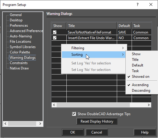
 Sorting Columns in the appropriate order
Columns can be sorted in two ways:
Sorting Columns in the appropriate order
Columns can be sorted in two ways:
- Via left click at the header of the appropriate column
- Via local menu command. This local menu can be called via a right click within the list.
For the Time Column, the default sets the time in ascending order.
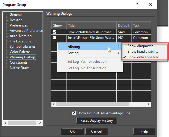
 Filtering the contents of the list
The ability to filter the contents of the list is available via the local menu. This local menu can be called via a right click within the list
The filtering commands are:
Filtering the contents of the list
The ability to filter the contents of the list is available via the local menu. This local menu can be called via a right click within the list
The filtering commands are:
- Show diagnostic - in addition to displaying normal content, the list also shows diagnostic messages. FALSE by default.
- Show fixed visibility - in addition to the normal content of the list also show messages for which the 'Show' state cannot be changed. FALSE by default.
- Show only appeared - Show only those warnings which have already appeared. If this option TRUE the content of the list is equal to the contents of this list in the all previous DoubleCAD versions. TRUE by default.
 Changing Multiple 'Log' or "show' Settings
Since the cells in the 'Log' column can have only two values ('Yes' and 'No'), it is convenient to change the value for the multiple selected cells (it is also possible to do this with the 'Show' column). This is possible through the local menu.
For Log:
Simply use Click and SHIFT to select the cells, then open the local menu and select the appropriate yes or no option.
For Show
Simply use Click and SHIFT to select the cells, check or uncheck the option box.
Changing Multiple 'Log' or "show' Settings
Since the cells in the 'Log' column can have only two values ('Yes' and 'No'), it is convenient to change the value for the multiple selected cells (it is also possible to do this with the 'Show' column). This is possible through the local menu.
For Log:
Simply use Click and SHIFT to select the cells, then open the local menu and select the appropriate yes or no option.
For Show
Simply use Click and SHIFT to select the cells, check or uncheck the option box.